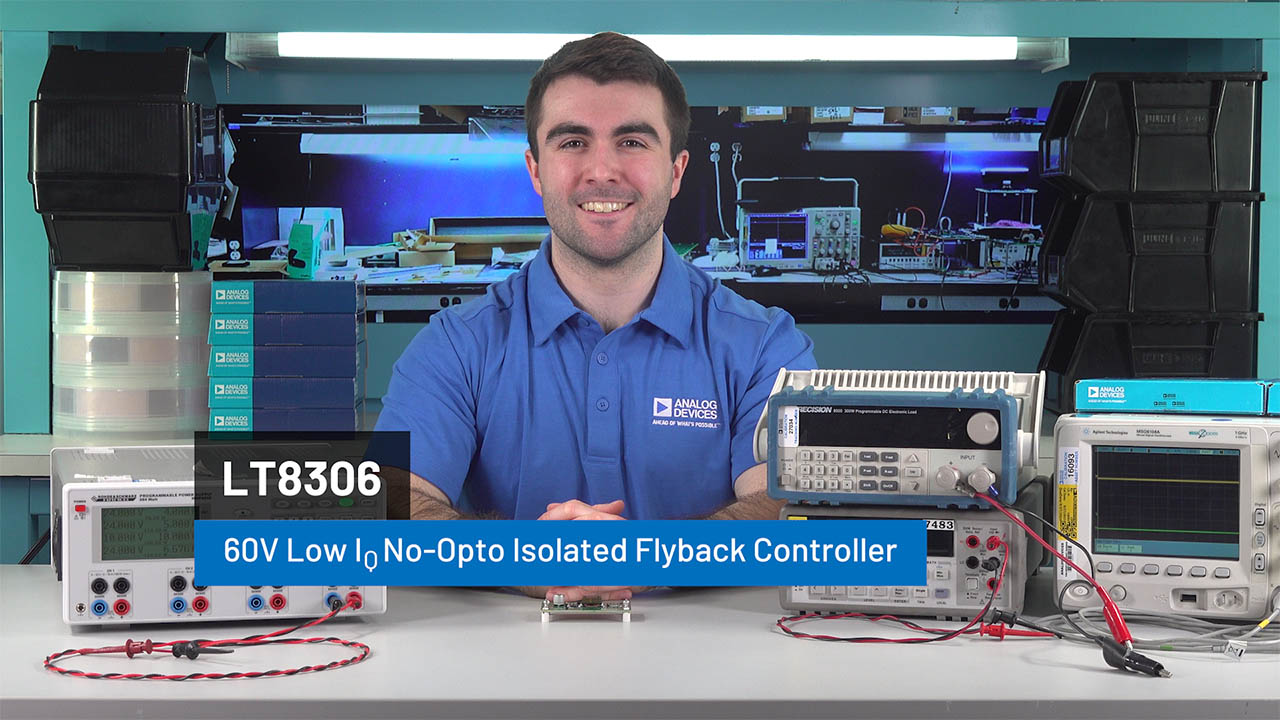
LT8306
Info : RECOMMENDED FOR NEW DESIGNS
searchIcon
cartIcon

LT8306

60V Low IQ No-Opto Isolated Flyback Controller

Show More showmore-icon

Info : RECOMMENDED FOR NEW DESIGNS tooltip
Part Details
Part Models 4
1ku List Price Starting From $0.79
Features
  • Wide Input Voltage Range: 4.5V to 60V
  • Low Quiescent Current
    • 120μA in Sleep Mode
    • 390μA in Active Mode
  • Quasi-Resonant Boundary Mode Operation at Heavy Load
  • Low Ripple Burst Mode® Operation at Light Load
  • Minimum Load < 0.5% (Typ) of Full Output
  • VOUT Set with a Single External Resistor
  • 8V Gate Drive for External NFET
  • No Transformer Third Winding or Opto-Isolator Required for Regulation
  • Accurate EN/UVLO Threshold and Hysteresis
  • Internal Compensation and Soft-Start
  • Output Short-Circuit Protection
  • 6-Lead TSOT-23 Package
  • AEC-Q100 Qualified for Automotive Applications
Additional Details
show more Icon

The LT8306 is a micropower isolated flyback controller in a 6-lead ThinSOT package. By sampling the isolated output voltage directly from the primary-side flyback waveform, the part requires no third winding or opto-isolator for regulation. The output voltage is programmed with a single external resistor. Internal compensation and soft-start further reduce external component count. Boundary mode operation provides a small magnetic solution with excellent load regulation. Low ripple burst mode operation maintains high efficiency at light load while minimizing the output voltage ripple. The LT8306 drives a low side N-channel power MOSFET with 8V gate drive.

The LT8306 has a wide input voltage range of 4.5V to 60V. The high level of integration and the use of boundary and low ripple burst modes result in a simple-to-use, low component count, and high efficiency application solution for isolated power delivery.

APPLICATIONS

  • Isolated Telecom, Automotive, Industrial, Medical Power Supplies
  • Isolated Auxiliary/Housekeeping Power Supplies
Part Models 4
1ku List Price Starting From $0.79

close icon
Documentation

Documentation

Video

Part Model Pin/Package Drawing Documentation CAD Symbols, Footprints, and 3D Models
LT8306RS6#TRMPBF
  • HTML
  • HTML
LT8306RS6#TRPBF
  • HTML
  • HTML
LT8306RS6#WTRMPBF
  • HTML
  • HTML
LT8306RS6#WTRPBF
  • HTML
  • HTML
Software & Part Ecosystem

Software & Part Ecosystem

Evaluation Kit

Evaluation Kits 2

reference details image

EVAL-LT8306-AZ

Low IQ No-Opto Isolated Flyback Controller

zoom

EVAL-LT8306-AZ

Low IQ No-Opto Isolated Flyback Controller

Low IQ No-Opto Isolated Flyback Controller

Product Detail

The EVAL-LT8306-AZ evaluation circuit is a micro-powered no-opto isolated flyback converter that features the LT8306. This demo circuit outputs 12V and maintains tight regulation with a load current from 15mA to 2.0A and over an input voltage from 6V to 36V. The output current capability increases with the input voltage.

The EVAL-LT8306-AZ needs very small minimum load (15mA) to regulate the output voltage because of the LT8306 ultra-low switching frequency at very light load. To properly limit the output voltage and avoid preloading under a no-load condition, a 13V zener diode is placed between the VOUT+ and VOUT- pins.

Transformer leakage inductance causes a voltage spike on the primary side after the power switch turns off. To limit this leakage inductance spike within a MOSFET voltage rating of 120V, an RC snubber and a TVS clamp are installed to dampen the ringing and clamp the MOSFET drain voltage to a safe level. The RC snubber can be removed to improve the efficiency by 3–4% when the load is below 100mA at 24V typical input.

The Performance Summary table in the user guide summarizes the performance of the evaluation circuit at room temperature. The evaluation circuit can be easily modified for different applications with some predesigned transformers.

The LT8306 is a simple-to-use micropowered isolated flyback controller. By sampling the isolated output voltage directly from the primary-side flyback waveform, the IC does not require a third winding or an opto-isolator for regulation. The IC sets the isolated output voltage with a single external resistor. It integrates loop compensation and an internal soft-start circuit to reduce external components. Boundary mode operation provides a small magnetic solution with excellent load regulation. The low-ripple burst mode operation maintains high efficiency at light load while minimizing the output voltage ripple.

The LT8306 is packaged in a 6-lead ThinSOT. It is AEC-Q100 qualified for automotive applications. The LT8306 data sheet gives a complete part description, operation, and applications information. Refer to the data sheet in conjunction with the EVAL-LT8306-AZ evaluation circuit quick start guide.

reference details image

AD-PS3803-RD

PoE+ with Ideal Diode Bridge to Isolated Flyback DC/DC (12V, 2A)

zoom

AD-PS3803-RD

PoE+ with Ideal Diode Bridge to Isolated Flyback DC/DC (12V, 2A)

PoE+ with Ideal Diode Bridge to Isolated Flyback DC/DC (12V, 2A)

Features and Benefits

  • Galvanically isolated 12V flyback DC output with up to 24 W of output power capability
  • No Transformer third winding or Opto-Isolator for output regulation
  • Supports IEEE802.3at (PoE+, Type 2) and IEEE802.3bt (PoE++, Type 3 and 4) interfacing and power supply control via a configurable jumper array
  • Supports a wide input DC auxiliary power of 37V to 57V

Product Detail

The AD-PS3803-RD reference design is a power converter capable of harnessing any IEEE802.3at (PoE+, Type 2) compliant downstream Power-Over-Ethernet (PoE) supply to provide a galvanically isolated DC power.

At the core of this solution is the LT8306 60V No-Opto Flyback controller, stepping down the 37V to 57V PoE input voltage to a 12V, 24W DC output.

The on-board LT4275 LTPoE++/PoE+/PoE power delivery (PD) controller handles interfacing and power delivery to any PoE supply.

The LT4321 ideal diode bridge controller is used for improved end-to-end power delivery efficiency and eased thermal design by utilizing low RDS(ON) N-Channel FETs, replacing the eight-diode configuration typically found in passive PoE rectifier bridge.

The AD-PS3803-RD also has auxiliary DC power support for a wide input range of 37V to 57V.

APPLICATIONS

  • Industrial Automation
  • Surveillance Camera Systems
  • VoIP Phones
  • Payment Terminal Systems
  • Wireless Access Points
Tools & Simulations

Tools & Simulations 1

LTspice® is a powerful, fast and free simulation software, schematic capture and waveform viewer with enhancements and models for improving the simulation of analog circuits.

To launch ready-to-run LTspice demonstration circuits for this part:

Step 1: Download and install LTspice on your computer.

Step 2: Click on the link in the section below to download a demonstration circuit.

Step 3: If LTspice does not automatically open after clicking the link below, you can instead run the simulation by right clicking on the link and selecting “Save Target As.” After saving the file to your computer, start LTspice and open the demonstration circuit by selecting ‘Open’ from the ‘File’ menu.

Recently Viewed