ADPA9005

RECOMMENDED FOR NEW DESIGNS

1GHz to 28GHz, 37.5dBm, GaN Power Amplifier

ADPA9005, 1-28GHz, 37.5dBm PA

Viewing:

Overview

  • Frequency range: 1GHz to 28GHz
  • Internally matched and AC-coupled input and output
  • Integrated temperature-compensated RF power detector
  • Power gain: 9.5dB typical with PIN = 28.0dBm from 6GHz to 25GHz
  • POUT: 37.5dBm typical with PIN = 28.0dBm from 6GHz to 25GHz
  • Small signal gain: 20.5dB typical from 6GHz to 25GHz
  • OIP3: 39.5dBm typical from 6GHz to 25GHz
  • VDD: 20V typical
  • IDQ: 560mA
  • 14-terminal, 7mm × 7mm, LCC_HS package
ADPA9005
1GHz to 28GHz, 37.5dBm, GaN Power Amplifier
ADPA9005 Functional Block Diagram ADPA9005 Typical Application Circuit ADPA9005 Pin Configuration
Add to myAnalog

Add product to the Products section of myAnalog (to receive notifications), to an existing project or to a new project.

Create New Project
Ask a Question

Documentation

Learn More
Add to myAnalog

Add media to the Resources section of myAnalog, to an existing project or to a new project.

Create New Project

Software Resources

EM-Plugs NEW

EM-Based RF Digital Twin Models

View Details

Tools & Simulations


Evaluation Kits

eval board
EVAL-ADPA9005

Evaluating the ADPA9005 1GHz to 28GHz, 37.5dBm, GaN Power Amplifier

Features and Benefits

  • 4-layer Rogers 4003C evaluation board with heat spreader
  • End launch, 2.92mm RF connectors
  • Through calibration path

Product Details

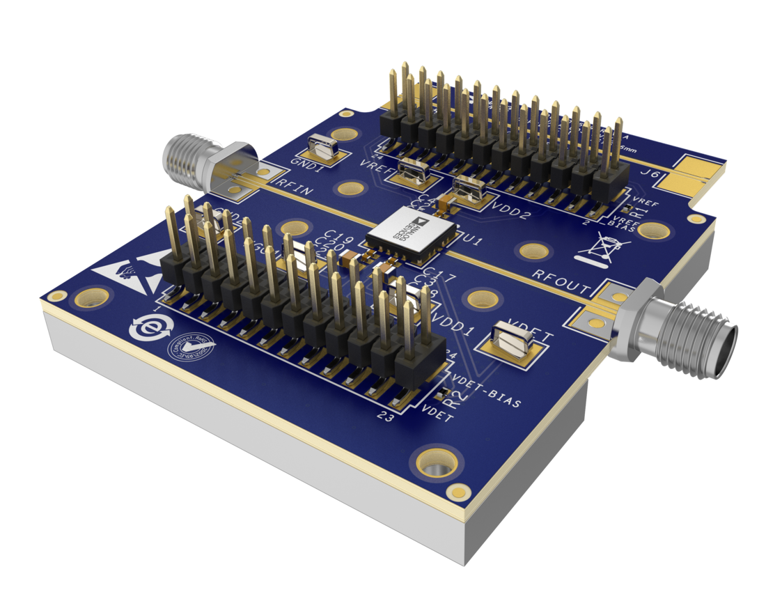
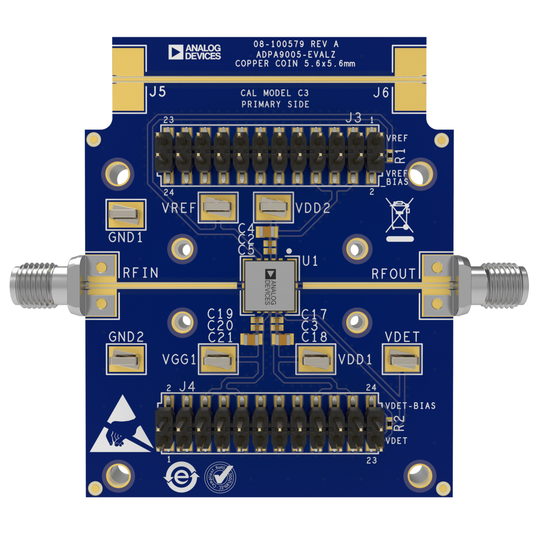
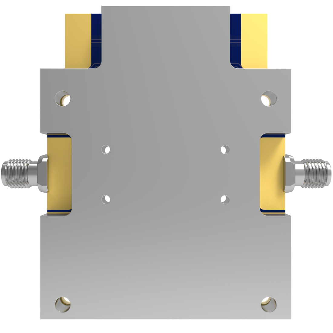
The ADPA9005-EVALZ consist of a 4-layer printed circuit board (PCB) fabricated from 8mil thick Rogers 4003C copper clad, forming a nominal thickness of 64 mils, mounted to an aluminum heat spreader. The evaluation board incorporates a copper coin beneath the exposed paddle of the ADPA9005, in addition to the heat spreader, providing enhanced thermal dissipation and mechanical support for the PCB. The mounting holes on the heat spreader allow attachment to larger heatsinks to improve thermal management. The RFIN and RFOUT ports are populated by 2.92mm female coaxial connectors, and their respective RF traces are of 50Ω characteristic impedance. The ADPA9005-EVALZ is populated with components suitable for use over the entire operating temperature range of the ADPA9005.

The RF transmission lines are 50Ω grounded coplanar waveguides. The package ground leads and the exposed pad connect directly to the ground plane. Multiple vias are used to connect the top and bottom ground planes, with particular focus on the area directly beneath the ground paddle to provide adequate electrical conduction and thermal conduction to the heat spreader.

The power supply decoupling capacitors shown in Figure 5 in the data sheet represent the configuration used to characterize the device.

For full details on the ADPA9005, see the ADPA9005 data sheet, which must be consulted in conjunction with this user guide when using the ADPA9005-EVALZ evaluation board.

EVAL-ADPA9005
Evaluating the ADPA9005 1GHz to 28GHz, 37.5dBm, GaN Power Amplifier
ADPA9005-EVALZ Top Angle Evaluation Board ADPA9005-EVALZ Top Evaluation Board ADPA9005-EVALZ Bottom Evaluation Board

Latest Discussions

No discussions on ADPA9005 yet. Have something to say?

Start a Discussion on EngineerZone®

Recently Viewed