µModule Regulator Combines a Switcher with Five 1.1A LDOs: Use Them for Multiple Low Noise Rails, or Parallel Them to Spread Heat and Share Current to 5A
µModule Regulator Combines a Switcher with Five 1.1A LDOs: Use Them for Multiple Low Noise Rails, or Parallel Them to Spread Heat and Share Current to 5A
2014-01-01
LDOs are often used as ripple-rejecting post-regulators on the outputs of switching converters. LDO post-regulators can also improve regulation and transient response. One of the top limitations on the output current capability for a post-regulator is the LDO temperature rise, which, aside from thermal resistance, depends mainly on its input-to-output differential voltage. The LTM8001 µModule regulator is a high efficiency step-down switching converter followed by an array of five low noise LDOs with individually rated output currents of 1.1A. To spread heat and increase available output current, the LDOs can be operated in parallel, giving designers several easy-to-implement options for varied input-output voltage combinations.
Some LTM8001 Features
Step-Down Converter
- 6V to 36V VIN range
- Constant voltage/constant current (CV/CC) output
- 5A maximum output current
- Adjustable 200kHz to 1MHz switching frequency
- Adjustable output voltage
LDOs
- Adjustable output voltages
- Three LDOs hardwired to the switcher output
- Two undedicated LDOs
Spread the Heat by Paralleling the LDOs
The LTM8001’s internal LDOs are typically set up to post-regulate the output of the built-in switching converter. An LDO’s temperature rise is relatively proportional to its output current, but it also produces more heat as its input-to-output differential voltage increases. When the input-to-output differential is low, approaching the dropout voltage, the LDO can operate close to its rated output current. It therefore makes sense to set the switcher output near the minimum input voltage of the highest voltage output LDO.
Furthermore, if the LDOs produce multiple output voltages, LDO output current must be derated for those LDOs with relatively low output voltages (i.e., those with higher voltages from input to output) to avoid excessive temperature rise. Nevertheless, any derated current can easily be recovered by paralleling the LDOs to both spread heat and multiply the current capability. The circuits in Figure 1 and Figure 2 show two schemes for operating LDOs in parallel to increase output current and spread heat.

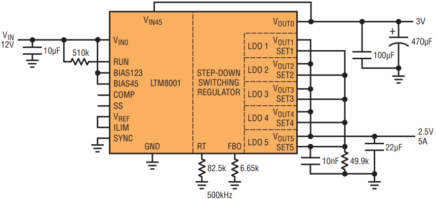
Figure 1. When operated in parallel, the five LDOs of the LTM8001 can provide a single 5A output. The input-to-output differential voltage for each LDO is relatively low, 500mV, so each can be operated at 1A, near its rated 1.1A.

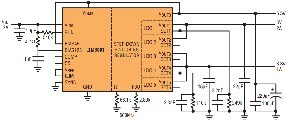
Figure 2. A solution optimized for dual low noise outputs. The 5V LDO output features the same low 500mV input-to-output differential voltage as in Figure 1, so LDOs 1 and 2 are operated near their rated currents. The input-to-output differential voltage for the 3.3V output is higher, so the available current from each of the three paralleled LDOs (3, 4 and 5) is derated to 330mA, for a combined 1A.
2.5V, 5A Regulator
In Figure 1, all five LDOs are combined in parallel to produce a single 2.5V, 5A output. In this case, the LTM8001’s built-in switching converter produces an output at 3V, 500mV above the 2.5V output of the LDOs. This input-to-output differential voltage is low enough to allow the LDOs to operate near their rated load current of 1.1A. Maximum current for the output is 5A with an input supply of 12V. The choice of a 500mV differential is based on a combination of parameters: the desired maximum output current, dropout margin when accounting for part-to-part variation, effect of operating temperature and transient response performance.
Dual Output Regulator Optimized for Low Noise
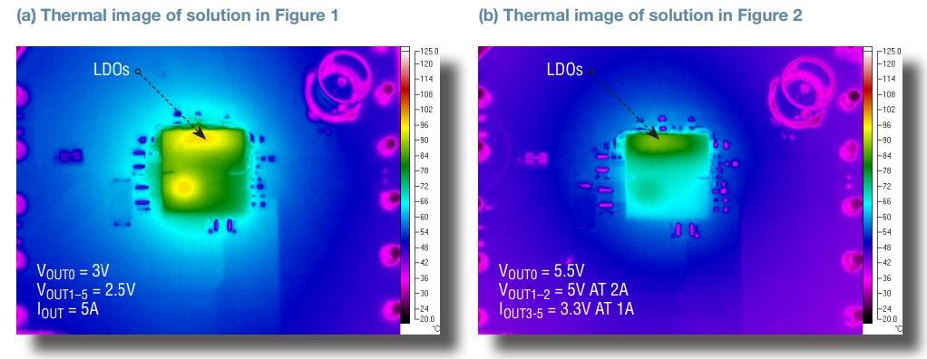
In Figure 2, the input supply is also 12V, but it produces two LDO outputs at 5V and 3.3V. The 5V LDO output has the same low 500mV input-to-output differential voltage as in Figure 1, so LDOs 1 and 2 are operated near their rated currents. The input-to-output differential voltage for the 3.3V output is higher so the output currents for LDOs 3, 4 and 5 each require derating to 330mA. Nevertheless, the three LDOs in parallel perform heat-spreading, so the available combined output current of the derated LDOs increases to 1A. The thermal images in Figure 3 show comparable LDO temperatures for the solutions in Figures 1 and 2.

Figure 3. Thermal imaging shows comparable LDO temperatures for the circuits in Figures 1 (a) and 2 (b) when operated at maximum current, proving the versatility of the LTM8001 in spreading heat, even when applied in very different solutions.
Setting the BIAS
The BIAS inputs to the LDOs must be 1.6V higher (worst case) than the highest corresponding LDO output voltage. Consequently, in Figure 1, BIAS is taken from VIN, but in Figure 2, BIAS for the 5V-output LDOs comes from VIN and BIAS for the 3.3V-output LDOs comes from the 5.5V switcher output (VOUT0).
Optimizing Output Noise
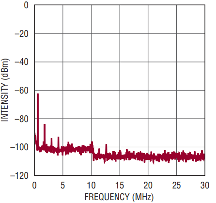
LDOs can be used to post-regulate the outputs of switching converters to produce low noise voltages because LDOs reject voltage ripple on both the switching converter output and the BIAS inputs to the LDO. The solution in Figure 2 is optimized for low noise outputs. The capacitance on the switching converter output VOUT0 and LDO outputs VOUT1–VOUT5 are optimized to minimize voltage ripple. The bias input BIAS45 from VIN is filtered. The LDO reference is a source of noise so capacitors are added to SET1–SET5 to bypass the LDO references. Figure 4 shows that the noise spectrum first harmonic peak is –63dBm for the 5V LDO1-LDO2 output in Figure 2.

Figure 4. The solution in Figure 2 is optimized for a low noise output. The 5V output produces a noise spectrum first harmonic peak of –63dBm.
Conclusion
The LTM8001 is a high efficiency step-down converter that is followed by five in-package low noise LDOs for a total output current capability of 5A. The outputs of the LDOs can be used to produce five different output voltages, or combined in a variety of parallel arrangements for high current outputs and heat spreading.


