Harvest Energy from a Single Photovoltaic Cell
To simplify the distribution of wireless communications for instrumentation, monitoring and control applications, power supply designers strive for device grid-independence. Batteries, the immediately obvious solution, offer the illusion of grid independence, but require replacement or recharging, which means eventual connection to the grid and expensive human intervention and maintenance. Enter energy harvesting, where energy is collected from the instrument’s immediate environment, offering perpetual operation with no connection to the grid and minimal or no maintenance requirements.
A variety of ambient energy sources can be harvested to produce electrical power, including mechanical vibration, temperature differential and incident light. Analog Devices produces power management solutions that solve the problems specific to harvesting ambient low energy sources, including the LTC3588 for vibration sources, the LTC3108/LTC3109 for thermal, and now the LTC3105 for photovoltaic energy harvesting applications. Photovoltaic energy harvesting is widely applicable, given that light is almost universally available, photovoltaic (PV) cells are relatively low cost and they produce relatively high power compared to other ambient energy harvesting solutions. Because of its relatively high energy output, photovoltaic energy harvesting can be used to power wireless sensor nodes, as well as higher power battery charging applications to extend battery life, in some cases eliminating tethered charging altogether.
While high voltage stacks of series-connected photovoltaic cells are prolific, single PV-cell solutions are rare, due to the difficulty of generating useful power rails from the low voltage produced by a single PV cell under load. Few boost converters can produce outputs from a low voltage, relatively high impedance single PV cell. The LTC3105, however, is designed specifically to meet these challenges. Its ultralow 250mV start-up voltage and programmable maximum power point control allow it to generate the typical voltage rails (1.8V–5V) required for most applications from challenging PV sources.
Understanding Photovoltaic Cell Sources
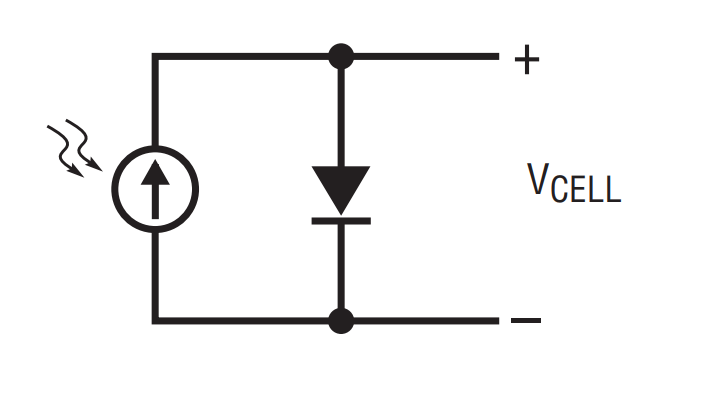
Photovoltaic sources can be electrically modeled by a current source connected in parallel with a diode as shown in Figure 1. More complex models show secondary effects, but for our purposes this model is sufficient.

Figure 1. Simple photovoltaic cell model.
Two common parameters that characterize a PV cell are the open circuit voltage and the short-circuit current. Typical curves for PV cell current and voltage are shown in Figure 2. Note that the short-circuit current is the output of the model’s current generator while the open circuit voltage is the forward voltage of the model’s diode. As light levels increase, the current from the generator increases and the IV curves move up.

Figure 2. Typical photovoltaic cell IV curve.
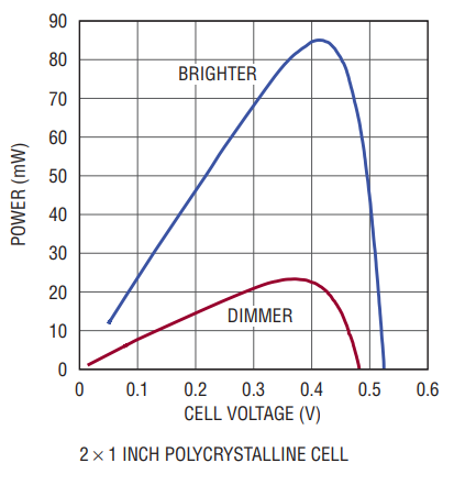
To extract maximum power from the PV cell, the input resistance of the power converter must be matched to the output resistance of the cell, resulting in operation at the maximum power point. Figure 3 shows the power curve for a typical single photovoltaic cell. To ensure maximum power extraction, the output voltage of the PV cell should be operated at the peak of the power curve. The LTC3105 adjusts the output current delivered to the load in order to maintain the PV cell voltage at the voltage set by the maximum power point control pin. Therefore, a single programming resistor establishes the maximum power point and ensures maximum power extraction from the PV cell and peak output charging current.

Figure 3. Typical photovoltaic cell power curve.
How Much Power Is Available?
The amount of power that can be generated using a photovoltaic cell depends on a number of factors. The output power of the cell is proportional to the brightness of the light landing on the cell, the total area of the cell, and the efficiency of the cell. Most PV cells are rated for use under full direct sunlight (1000W/m2), but such ideal conditions are unlikely to occur in most applications. For devices operating from sunlight, the peak power available from the cell can easily change by a factor of ten from day to day due to weather, season, haze, dust, and incident angle of the sunlight. Typical output power for a crystalline cell in full sunlight is about 40mW per square inch depending on cell characteristics. A PV cell with an area of a few square inches is sufficient to run many remote sensors and to trickle charge a battery.
In contrast, devices operating from indoor lighting have far less energy available to them. Common indoor lighting is roughly 0.25% as strong as full sunlight (the huge difference in intensity between indoor lighting and sunlight is hard to perceive due to the human eye’s ability to adjust to a wide range of illumination levels). The dramatically lower light levels available to indoor applications presents design challenges. Even a large high efficiency crystalline cell with an area of four square inches generates only 860µW in typical office lighting.
Choosing The Maximum Power Point Control Voltage
Figure 4 shows a model of the maximum power point control mechanism used by the LTC3105. Figure 3 shows the power curve for a PV cell. Note that PV cell power declines sharply from its peak as the cell voltage rises away from peak power. It is thus generally more desirable to err on the side of a lower than-ideal control voltage, rather than a higher voltage, because the power curve rolls off more sharply on the high side.

Figure 4. Maximum power point control mechanism.
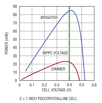
When selecting the MPPC tracking voltage, various operating conditions must be considered. Typically, the maximum power point does not move substantially with changes in illumination. As a result, it is possible to choose a single tracking voltage that provides operation near the maximum power point for a wide range of illumination levels. Even though the operating point will not be precisely at the maximum power point at extreme levels of illumination, the reduction in output power from the ideal is usually only 5%–10%.
For the power curve shown in Figure 5, an MPPC voltage of 0.4V yields performance near the maximum power point at either illumination extreme. The voltage difference from the maximum power point is approximately 20mV in both cases, resulting in a power loss of less than 3%.

Figure 5. Err on the side of a lower voltage when choosing a maximum power point voltage to avoid the steep drop-off.
As a rule of thumb, the maximum power point control voltage should be around 75%–80% of the open circuit voltage for the PV cell. Tracking the cell to this voltage results in a cell output current that is 75%–80% of the short-circuit current.
Li-Ion Battery Charging In Outdoor Lighting
One of the challenges faced by applications using a photovoltaic source is the lack of input power during darkness and low light conditions. For most applications this necessitates use of energy storage elements such as a supercapacitor or rechargeable battery that is large enough to provide power throughout the longest expected dark period.
Figure 7 shows the measured charging current profile using a 2” × 1” polycrystalline PV cell to charge a Li-ion battery using the LTC3105 circuit shown in Figure 6. The upper curve of Figure 7 shows the charging current on a typical clear day with full sun. The lower curve shows the charging current observed over the course of a heavily overcast day. Even under these low light conditions a charging current of 250µA or more was maintained throughout the day totaling 6mAh of charge delivered to the battery.

Figure 6. Li-ion charging circuit.

Figure 7. Charging profiles for two square inch photovoltaic cell.
Choosing The Right Energy Storage Device
There are many alternatives for storing harvested energy, including a wide variety of rechargeable battery technologies and high energy density capacitors. No one technology is perfect for all applications. When selecting the storage element for your application, consider a number of factors, including the self-discharge rate, maximum charge and discharge current, voltage sensitivity, and cycle lifetime.
The self-discharge rate is particularly important in photovoltaic applications. Given the limited amount of charging current available in most photovoltaic power applications, a high self-discharge rate may consume a large portion of the available energy from the PV source. Some energy storage elements, such as large supercapacitors, may have self-discharge current in excess of 100µA, which could dramatically reduce the net charge accumulated over a daily charge cycle.
Another key consideration is the rate at which the energy storage device can be charged. For example, a lithium coin cell with a maximum charging current of 300µA requires a large resistor between it and the output of the LTC3105 in order to prevent overcurrent conditions. This can put a limit on the amount of energy harvested, decreasing the amount of energy available to the application.
In many cases the charge rate is proportional to another important factor, cycle lifetime. The cycle life of a storage element determines how long it can operate in the field without maintenance. Generally, faster charging and discharging reduces the operational life of the element. Supercapacitors offer very good cycle life, while batteries charged with relatively high currents (charge > 1C) have degraded lifetimes. In addition to the charge and discharge rate, the depth of each charge/discharge cycle can affect the lifetime of batteries, with deeper cycles leading to shorter life times.
With several battery types, notably lithium and thin film, the maximum and minimum voltage must be carefully controlled. The maximum charge voltage is well controlled in LTC3105 applications since the converter terminates charging when the output comes into regulation. To prevent over-discharge, the LTC3105 can be used in conjunction with the LTC4071 shunt battery charger as shown in Figure 8.

Figure 8. A Li-ion trickle charger operates from a single photovoltaic cell.

Figure 9. Single-cell photovoltaic NiMH trickle charger.

Figure 10. Single-cell-powered remote wireless sensor.
Conclusion
The LTC3105 is a complete single chip solution for energy harvesting from low cost, single photovoltaic cells. Its integrated maximum power point control and low voltage start-up functionality enable direct operation from a single PV cell and ensure optimal energy extraction. The LTC3105 can be used to directly power circuitry or for charging energy storage devices to allow operation through dark or low light periods. The LTC3105 makes it possible to produce autonomous remote sensor nodes, data collection systems and other applications that require grid independence and minimal maintenance.


