摘要
本系列第一部分围绕元件失效率及可靠性预测方法展开了讨论。第二部分将介绍失效模式、影响及诊断分析(FMEDA)。作为系统集成商可采用的安全分析工具之一,FMEDA能依据IEC 61508等功能安全标准的要求,对安全相关系统的设计进行评估。开展FMEDA分析需要获取多项元件信息,其中包括失效率数据和失效模式分布(FMD)。本文将阐述FMD等因素如何影响FMEDA评估,并介绍ADI公司的安全应用笔记如何提供此类信息。
什么是FMEA?
失效模式和影响分析(FMEA)是一种安全分析工具或方法,用于评估系统或流程,明确可能出现的失效形式,了解这些失效模式对相关项目的性能和周边环境造成的影响。通常,FMEA会通过迭代方式实施,为降低失效发生概率及减轻失效影响的决策提供支持,进而助力提升系统和流程的稳健性与可靠性。1
图1展示了典型FMEA的构成要素及其一些广为人知的变体:FMECA 和FMEDA。FMEA通常基于以下信息:系统或流程的相关信息、待分析的功能、组成系统的组件、每个组件的失效模式、局部及全局影响等。当FMEA根据失效模式的重要性对其进行优先级排序时,称为失效模式、影响及危害性分析(FMECA)。当FMEA采用某种度量方式来体现诊断功能的有效性时,则称为失效模式、影响及诊断分析(FMEDA)。1,2


在安全相关系统的设计中,FMEDA通常用于以下方面:提供与每种失效模式对应的器件级失效率;衡量自动诊断功能的有效性;在设计决策中应用定量可靠性分析;证明最终设计优于其他备选方案;表明硬件设计符合IEC 61508标准的要求。2
示例FMEDA
表1呈现了一个源自IEC 60812:2018标准的FMEDA示例。尽管该示例并不完整1,但仍展示了电源电路主要部分的评估方法。该电源电路采用线性稳压器为器件内部提供电源电压。
此FMEDA示例包含多种失效率数值,具体有安全失效率(λS)、无影响失效率(λNE)、危险可检测失效率(λDD)和危险不可检测失效率(λDU ),这些都是计算安全失效比率(SFF)的重要参数。1
表1. 电源电路的FMEDA分析(基于IEC 60812:2018 标准表F.12)
| 名称 | 元件 | 功能 | 失效率(FIT) | 失效模式 | FMD | 影响 | 失效分类 | 诊断 覆盖率 | λS(FIT) | λNE(FIT) | λDD(FIT) | λDU(FIT) |
| F50 | 保险丝 | 短路保护(输入端) | 25 | 无法开路 | 50% | 正常运行 时无 | 无影响 | - | 0 | 12.5 | 0 | 0 |
| 过早开路 | 10% | 输出断电 | 安全 | - | 2.5 | 0 | 0 | 0 | ||||
| 开路缓慢 | 40% | 对安全功能无影响 | 无影响 | - | 0 | 10 | 0 | 0 | ||||
| D12 | 抑制二极管 | 过压保护(EMC) | 7 | 短路 | 95% | F50熔断 | 安全 | - | 6.65 | 0 | 0 | 0 |
| 开路 | 5% | 对安全功能无影响 | 无影响 | - | 0 | 0.35 | 0 | 0 | ||||
| R100 | 电阻,SMD | 电流限制(EMC) | 0.2 | 短路 | 5% | 无电流限制 | 危险 | 60% | 0 | 0 | 0.006 | 0.004 |
| 开路 | 65% | 输出断电 | 安全 | - | 0.13 | 0 | 0 | 0 | ||||
| 参数变化 | 30% | 功能仍正常 | 无影响 | - | 0 | 0.06 | 0 | 0 | ||||
| C13 | 陶瓷电容,HDC/MDC | EMC | 2 | 短路 | 50% | F50熔断 | 安全 | - | 1 | 0 | 0 | 0 |
| 开路 | 30% | 正常运行 时无 (无保护) | 无影响 | - | 0 | 0.6 | 0 | 0 | ||||
| 值变化 | 20% | 功能仍正常 | 无影响 | - | 0 | 0.4 | 0 | 0 | ||||
| D25 | 小信号 二极管 < 0.1 W <0.1 W |
电桥整流器 | 1 | 短路 | 50% | F50熔断 | 安全 | - | 0.5 | 0 | 0.006 | 0 |
| 开路 | 35% | 在交流供电情况下无法正常整流 | 安全 | - | 0.35 | 0 | 0 | 0 | ||||
| 参数变化 | 15% | 功能仍正常 | 无影响 | - | 0 | 0.15 | 0 | 0 | ||||
| C2 | 电解电容,铝电解电容,非固体电解质 | 滤波电容 | 5 | 短路 | 53% | F50熔断 | 安全 | - | 2.65 | 0 | 0 | 0 |
| 开路 | 35% | 直流供电 下正常运行时无 | 无影响 | - | 0 | 1.75 | 0 | 0 | ||||
| 电解液泄漏 | 10% | 对安全功能无影响 | 安全 | - | 0 | 0.5 | 0 | 0 | ||||
| 电容减少 | 2% | 功能仍正常 | 无影响 | - | 0 | 0.1 | 0 | 0 | ||||
| IC18 | 稳压器, 功率> 1W, 低复杂度 | 与R100配合使用的稳压器,用作电流源 | 25 | 高电平锁定 | 30% | 无调节功能-> 输出开关 | 危险 | 0% | 0 | 0 | 0 | 7.5 |
| 低电平锁定 | 30% | 输出断电 | 安全 | - | 7.5 | 0 | 0 | 0 | ||||
| 短路 | 15% | 无调节功能-> 继电器过电流 (多样) | 无影响 | - | 0 | 3.75 | 0 | 0 | ||||
| 开路 | 15% | 输出断电 | 安全 | - | 3.75 | 0 | 0 | 0 | ||||
| 漂移 | 5% | 功能仍正常 | 安全 | - | 0 | 1.25 | 0 | 0 | ||||
| 功能 | 5% | 功能仍正常 | 无影响 | - | 0 | 1.25 | 0 | 0 | ||||
| 小计 | 25.03 | 32.66 | 0.006 | 7.504 | ||||||||
计算 SFF3:

现有诊断功能对R100短路失效的诊断覆盖率仅为60%,对IC18的危险失效的诊断覆盖率为0%,据此计算得出SFF为76.94%。若该电源电路仅设计用于单通道系统,则其仅能达到SIL 1。3若增加针对IC18危险失效的诊断功能,此设计可进一步改进,以达到更高的SIL等级。当新增的诊断功能对IC18危险失效的诊断覆盖率达到99%时,其对应的 λDU将从7.5 FIT降至0.075 FIT,而λDD将从0.006 FIT增至7.431 FIT,新的总 λDU为0.079 FIT,因此SFF为99.76%。
计算 PFH4:


同时,该电源电路的总 λDU需符合IEC 615083标准中关于危险失效概率的要求。降低与安全相关的系统总 λDU(包括电源电路及其诊断功能),将对应降低每小时危险失效的平均频率(PFH),从而更易满足更高的安全完整性等级(SIL)要求。4
值得注意的是,有三列数据会影响失效模式、影响及诊断分析(FMEDA)的失效率结果,如表1所示。这些列分别涉及:元器件的失效率、失效模式分布(FMD)以及诊断覆盖率。元器件失效率通常来自元器件制造商,也可通过可靠性预测方法进行计算。而失效模式分布(FMD)是指元器件总失效率中可分配至每种失效模式的比例,该分布通常也由元器件制造商提供。最后,诊断覆盖率指所用诊断功能对失效的检测能力,这是系统集成商在设计中唯一可优化的因素,可通过增加诊断功能或采用更优的诊断方法实现。
利用ADI的安全应用笔记加快系统的FMEDA进程
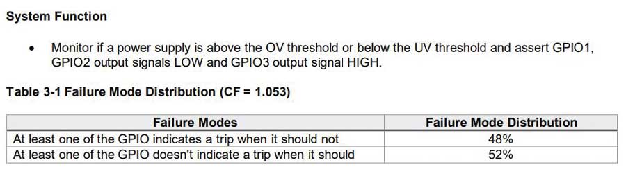
本系列的第一部分展示了 LTC2933的安全应用笔记如何基于不同的可靠性预测方法提供基础失效率数据。利用此类集成电路(IC)的失效率数据,并结合同一文档中如图2所示的现成失效模式分布(FMD)信息,可显著加快基于此类IC的系统FMEDA进程。此类安全应用笔记还会阐明假设的系统功能及IC使用的应用电路。
借助ADI公司的安全应用笔记,安全分析将变得更加准确,因为相关信息直接来自元器件制造商,而非简单地将全部失效率归为危险失效率,或基于特定假设来设定某种FMD。
结语
本文首先概述了一种名为FMEA(失效模式与影响分析)的安全分析工具,并介绍了其衍生形式FMECA(失效模式、影响及危害性分析)和FMEDA(失效模式、影响及诊断分析)。随后,本文深入剖析了一个FMEDA实例,阐释了整合诊断功能及其诊断覆盖率对于提升电源电路的安全失效比率(SFF)的作用。文章进一步强调,在考虑诊断功能的前提下,降低未检测到的危险失效率具有重要意义。最后,本文展示了系统集成商能够如何利用ADI公司安全应用笔记中提供的元器件FMD信息,提高系统FMEDA和安全分析的技术准确性。
参考文献
1 “IEC 60812:2018.Failure Modes and Effects Analysis (FMEA and FMECA)”,国际电工委员会,2018年。
2 Paddy Healy,“What Is a FMEDA??”,Exida,2023年4月。
3 “IEC 61508 All Parts, Functional Safety of Electrical/Electronic/Programmable Electronic Safety-Related Systems”,国际电工委员会,2010年。
4Loren Stewart,“Back to Basics 17 - PFH”,Exida,2019年11月。
