Constant Current from 3A DC/DC Converter with 2 Rail-to-Rail Current Sense Amplifiers
Constant Current from 3A DC/DC Converter with 2 Rail-to-Rail Current Sense Amplifiers
著者
Daniel Chen
2005年12月01日
Introduction
Traditional DC/DC converters use voltage feedback for constant output voltage regulation. There are many applications, however, that need to regulate a constant output current. Driving LEDs in series is one such application. The LT3477 combines a traditional voltage feedback loop and two unique current feedback loops to operate as a constant-current, constant-voltage source. It is a current mode, 3A DC/DC converter with dual rail-to-rail 100mV current sense amplifiers that can be configured as a buck mode or buck-boost mode LED driver. It is versatile enough to also be configured as an input-output current limited boost, SEPIC or inverting converter. Both current sense voltages can be adjusted independently using the IADJ1 and IADJ2 pins.
With two identical precision current sense amplifiers, the LT3477 can provide an accurate input current limit as well as an accurately regulated output current. With an input voltage range of 2.5V to 25V, the LT3477 works from a variety of input sources. The 42V switch rating allows an output voltage of up to 41V to be generated, easily driving up to ten white LEDs in series. The buck mode LED configuration is capable of driving multiple ten-LED strings in parallel if external current mirroring circuitry is added.
The switching frequency is adjustable from 200kHz to 3.5Mhz, set by a single resistor. The available high operating frequencies allow the use of low profile inductors and capacitors—important in applications where space is a premium. The wide available range makes it possible to optimize size and efficiency for your application.
How It Works
Figure 1 shows a block diagram of the LT3477. The voltage error amplifier has both FBP and FBN pins to allow a positive or negative output configuration. With the addition of two current feedback control loops, amplifier A3 becomes a summing point for three feedback loops. Depending on configuration, any of the loops can take over feedback control by sourcing or sinking current at the VC node. The unique feature of the three-feedback-loop topology (two current and one voltage) is that it can support constant voltage and/or constant current applications.
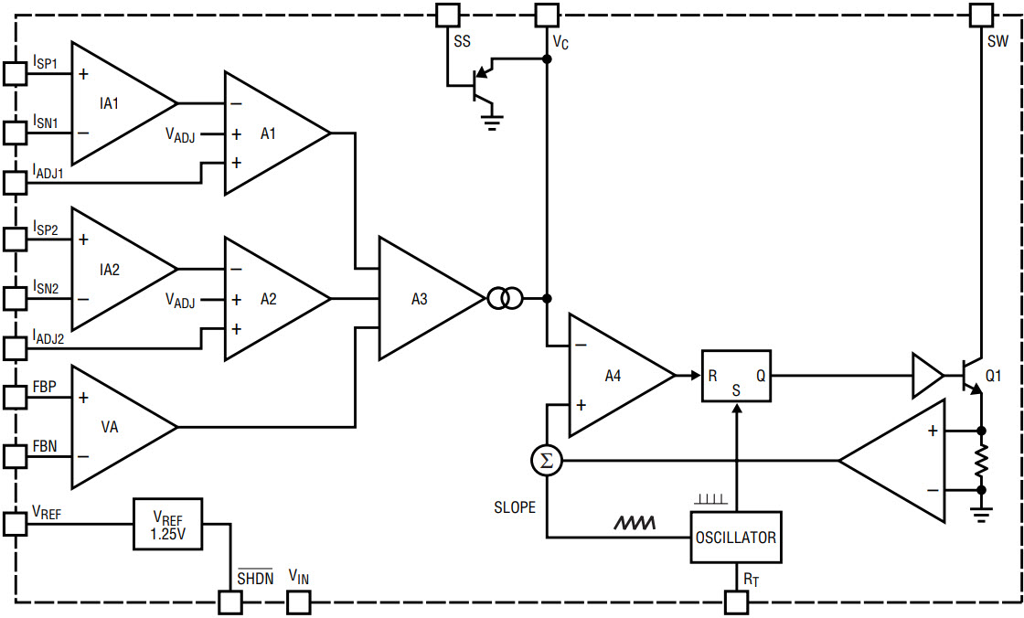
Figure 1. LT3477 block diagram.
Current sense levels are adjustable via sense resistors at the IADJ1 and IADJ2 pins. The default sense voltage is 100mV for each current sense amplifier if the IADJ1 and IADJ2 pins are tied to a potential higher than 650mV. If the potentials at the IADJ1 and IADJ2 pins are lower than 625mV, the LT3477 linearly adjusts the current sense level. Figure 2 shows the voltage sense level vs the IADJ pin voltage. For LED drivers, IADJ1 and IADJ2 pins can be used to adjust LED current levels. Rail-to-rail current sense amplifiers allow flexible current sense schemes.
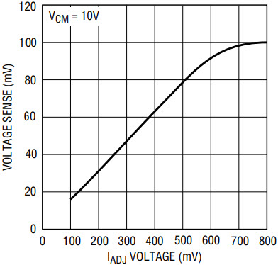
Figure 2. Current sense amplifier voltage sense level vs IADJ pin voltage.
Applications
Buck Mode High Current LED Driver
Figure 3 shows a typical application to drive high current LEDs. Traditionally, LED drivers use a grounded current sense resistor to regulate current, but the LT3477 current sense amplifiers work in a high side sense scheme, so the sensed voltage for current feedback no longer needs to be ground referred. In buck mode configuration, the sense resistor is placed right at the input supply. The LEDs are placed between the sense resistor and the inductor and the Schottky diode is connected between the SW and PVIN nodes. With high side current sense, the boost converter is effectively converted into a buck LED converter, which increases the part’s power handling capability. In addition, the VIN pin, which provides the chip operating current, can be tied to a lower voltage level such as 3.3V. As a result, the power consumption on the chip itself is also reduced, thus improving overall efficiency. Over 90% efficiency can be readily achieved with a wide range of inductor and frequency selections.
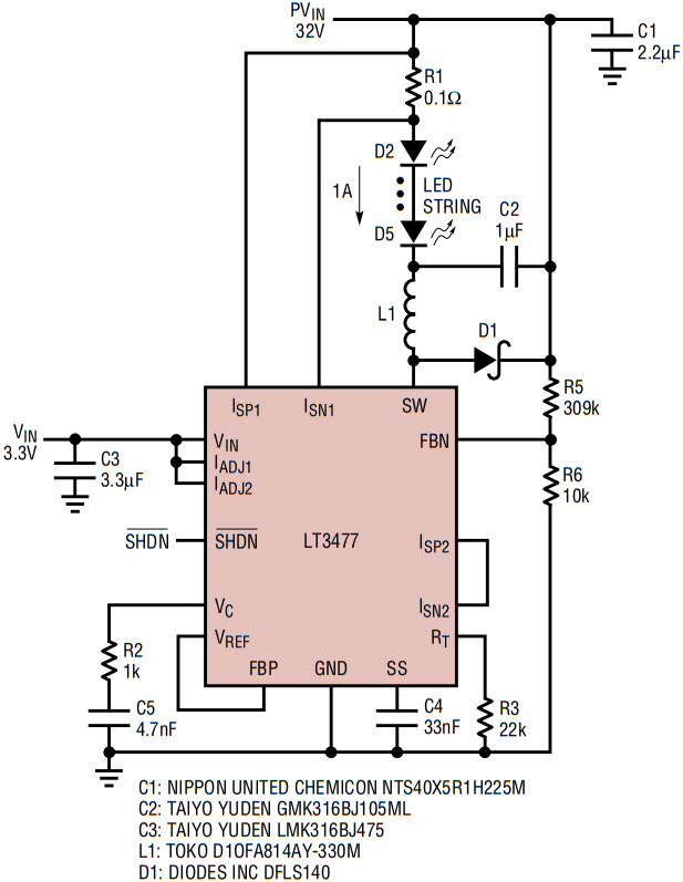
Figure 3. Buck mode high current LED driver.
Buck-Boost LED Driver
In some applications, the input voltage might be comparable to the total LED voltage drop or the input voltage might fluctuate to higher or lower than the total LED voltage drop. A buck-boost LED driver works well in this type of application. Figure 4 shows the LT3477 buck-boost LED driver. The cathode end of the LED string is tied back to the input voltage, which allows it to operate from a wide input voltage range. R5 and R6 in Figure 4 are used for open LED protection. Figure 5 is the efficiency measured for this circuit.
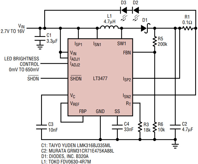
Figure 4. Buck-boost LED driver.
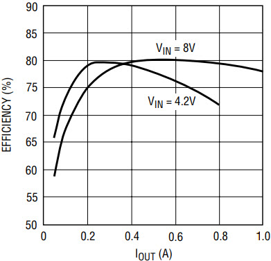
Figure 5. Buck-boost LED driver efficiency.
330mA LED Driver with Open LED Protection
LT3477 can also be used for LED driver applications using a conventional boost topology with the current sense amplifier for current regulation. Figure 6 shows a typical application circuit, and Figure 7 shows the efficiency. Figure 6 uses a high side current sense configuration for feedback control. The current sense amplifier could also be used for a grounded current sense for this application, if desired, so the output can be tied to the LED string directly. ISP2 would be tied to the cathode side of the LEDs, and ISN2 is tied to ground. Voltage feedback is used for open LED protection.
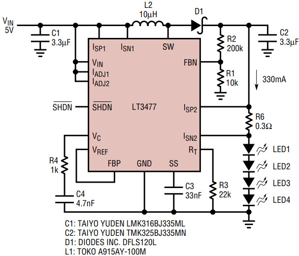
Figure 6. 4W LED driver.
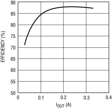
Figure 7. 4W LED driver efficiency.
5.5V SEPIC Converter with Short-Circuit Protection
Certain applications demand a converter output that is DC-isolated from the input. SEPICs (single-ended primary inductance converters) provide the solution. Figure 8 is an implementation which provides a 5.5V output with complete short-circuit protection. The current sense amplifier used for current sense not only provides excellent short-circuit protection, but also helps soft start the output. The accurate output current limit ensures the maximum current is set at 670mA. When the load demands more, the output voltage will droop while the 670mA output current is maintained. Efficiency is shown in Figure 9.
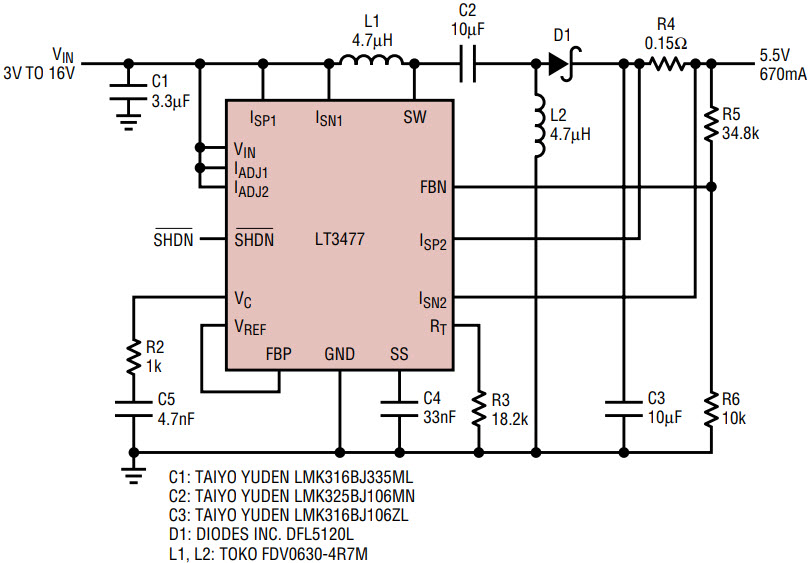
Figure 8. 5.5V SEPIC converter with short-circuit protection.
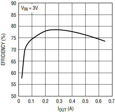
Figure 9. 5.5V SEPIC converter with short-circuit protection efficiency.
Cuk Converter
The LT3477 provides pins for both inputs to the voltage error amplifier, which enables negative output voltages. Figure 10 is an implementation using a Cuk topology for 5V to –5V conversion. The first current sense amplifier is used for input current limit, and the second current sense amplifier is used for ground rail current sense to accurately limit the load current at 500mA. Even though the two current sense amplifiers are used, efficiency up to 81% at 500mA output load can still be achieved. Figure 11 shows the efficiency.
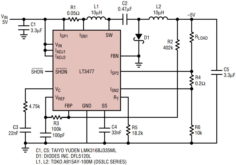
Figure 10. Negative output voltage Cuk converter.
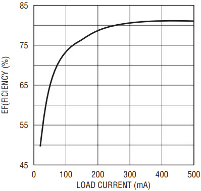
Figure 11. Efficiency of the Cuk converter.
Conclusion
The rail-to-rail constant-current/constant-voltage operation of the LT3477 makes the device an ideal choice for a variety of constant-current designs, including negative outputs. The dual current-sense amplifiers allow flexible configuration for input current limit, constant output current and fail-safe protection, along with excellent output voltage regulation. A wide input voltage range and the ability to produce outputs up to 42V make the LT3477 extremely versatile.


