要約
This application note describes how to properly access the clock registers in the DS1318 Elapsed Time Counter. Reads and writes to the real-time clock (RTC) and the internal updates of the clock registers are asynchronous events that must be arbitrated to ensure accurate data.
Pin Configuration

Description
The DS1318 parallel-interface elapsed-time counter (ETC) is a 44-bit counter that can provide the elapsed time with 244µs resolution. The ETC has six registers. Four of the registers represent a 32-bit value in seconds. The other two registers use 12 bits to maintain the subsecond count (Table 1). The DS1318 can be used to track the time and date. A zero value in the ETC registers must be defined as some particular "zero epoch." In Unix systems, for example, the zero epoch is Midnight, January 1, 1970. The 32-bit seconds register can be used to represent any time between Midnight January 1, 1970, and 03:14:07 January 19, 2038. Conversion routines are normally used to convert the 32-bit count to a standard time and date format. The DS1318 can also be used to count the elapsed time between two events.
| Address | Bit 7 | Bit 6 | Bit 5 | Bit 4 | Bit 3 | Bit 2 | Bit 1 | Bit 0 | Function | Range |
| 00H | SS3 | SS2 | SS1 | SS0 | 0 | 0 | 0 | SQWS | Subseconds0 | 00-F0h |
| 01H | SS11 | SS10 | SS9 | SS8 | SS7 | SS6 | SS5 | SS4 | Subseconds1 | 00-FFh |
| 02H | S7 | S6 | S5 | S4 | S3 | S2 | S1 | S0 | Seconds0 | 00-FFh |
| 03H | S15 | S14 | S13 | S12 | S11 | S10 | S9 | S8 | Seconds1 | 00-FFh |
| 04H | S23 | S22 | S21 | S20 | S19 | S18 | S17 | S16 | Seconds2 | 00-FFh |
| 05H | S31 | S30 | S29 | S28 | S27 | S26 | S25 | S24 | Seconds3 | 00-FFh |
| 06H | ALM 7 | ALM 6 | ALM 5 | ALM 4 | ALM 3 | ALM 2 | ALM 1 | ALM0 | Alarm0 | 00-FFh |
| 07H | ALM 15 | ALM 14 | ALM 13 | ALM 12 | ALM 11 | ALM 10 | ALM 9 | ALM 8 | Alarm1 | 00-FFh |
| 08H | ALM 23 | ALM 22 | ALM 21 | ALM 20 | ALM 19 | ALM 18 | ALM 17 | ALM 16 | Alarm2 | 00-FFh |
| 09H | ALM 31 | ALM 30 | ALM 29 | ALM 28 | ALM 27 | ALM 26 | ALM 25 | ALM 24 | Alarm3 | 00-FFh |
| 0AH | TE | ECOSC | CCFG1 | CCFG0 | EPOL | SQWE | PIE | AIE | ControlA | 00-FFh |
| 0BH | PRS3 | PRS2 | PRS1 | PRS0 | SRS3 | SRS2 | SRS1 | SRS0 | ControlB | 00-FFh |
| 0CH | OSF | UIP | 0 | 0 | 0 | 0 | PF | ALMF | Status | - |
In either of these applications, it is usually necessary to read the ETC while it is running. The DS1318 has a set of "user registers" that allow accessing the data while the internal counters continue to run. The user registers are updated from the internal registers every 244µs. Even though the counters are buffered, because the reads and counter updates can occur asynchronously, it is possible to read or write incorrect data.
Example 1
While reading the ETC, the data may update. If, for instance, the data in the registers was 0x55555555.FFF and an update occurred between reading the subseconds and seconds registers, the value read would be 0x55555556.FFF instead of 0x55555556.000.
Example 2
The data are transferred from the internal counters to the user registers as one of the registers is accessed. In this case, there is a window of a few nanoseconds where the data are changing just as they are being read. While the chances of this happening are low, the data, when it does occur, will be invalid.
Example 3
A write occurs while the data is being transferred between the internal counters and the user registers. Because the internal data bus is being used during the transfer, a write to any register in the DS1318 could corrupt the data (data collision). Again, the window when this can occur is only a few nanoseconds. The data in the user registers will be invalid until the next update, 244µs later.
Example 4
When writing the counter, if writing all the registers takes longer than 244µs, an update could occur, incrementing the data in previously written registers.
There are several ways to avoid these errors. The DS1318 contains two bits that can be used to avoid reading or writing during an update. The following paragraphs discuss the various methods.
An update could occur when reading the counter registers. One way to verify that the data read is correct is to read the appropriate registers, from LSB to MSB, store the results, and then read the registers again. If an update has occurred, the data from the first read will be different from the second read. If the data is different, the registers should be read again until the data match. If all the subseconds registers are used, an update will occur every 244µs. If only the seconds registers are being used, an update will occur once per second (Figure 1).

Figure 1. Reading the clock registers between updates.
When reading the counters, the update-in-progress (UIP) bit can be used to avoid an error. The UIP cycles every 244µs, and will read back as a 1 if an update occurs within 61µs. When reading the counter registers, the UIP bit should be checked. If it is 1, the reads should be delayed until UIP is 0. If UIP is 0, the registers can be read. The registers should be read within 60µs to avoid an update (Figure 2). If it is possible for the read routine to take longer than 60µs (i.e., the routine is interrupted by another routine that could take longer than 60µs), then precautions must be taken to make sure the data is valid.

Figure 2. Reading the clock registers using the UIP bit.
Another method of reading the registers uses the UIP bit and the transfer-enable (TE) bit. The TE bit, when set to 0, stops transfers between the internal counters and the user registers. Since the last transfer could be corrupted by the write to the TE bit, the UIP bit should be used to verify that an update will not occur when the TE bit is written. Once TE is set to 0, the data may be read from the registers. Since updates are inhibited, it does not matter if the UIP bit is set, or how long it takes to read the registers. This routine could be used instead of the previous one in applications where it may take longer than 60µs to read all the registers.
Once the data are read, the TE bit should be written to 1, enabling transfers. Note that the transfers must be enabled for at least 244µs for a transfer to occur. Because of this requirement, reading sequential values of the subseconds0 registers using this method is impossible (Figure 3).

Figure 3. Reading the clock registers using the UIP and TE bits.
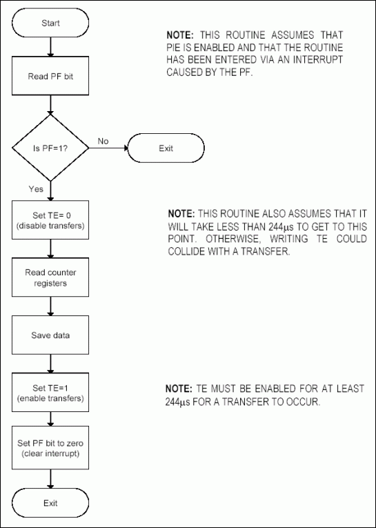
The periodic interrupt is synchronized with the update of the clock registers. If the PF flag is used with the interrupt output, the clock registers can be read immediately after an update. If the subseconds registers are being read, the next update will not occur for approximately 244µs. If only the seconds registers are being used, the next update will occur in one second. This routine could be used in applications where periodic updates of the time and date, i.e., for time and date display, are needed. Using the PF flag to drive the interrupt input on a microcontroller allows the system to perform other functions until the time value changes.

Figure 4. Reading the clock registers using the periodic interrupt flag.

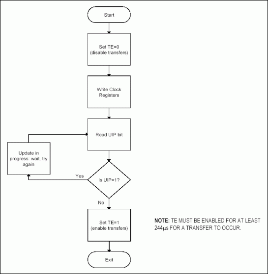
Figure 5. Writing the clock registers using the TE and UIP bits.
When writing data to the counter registers, the TE bit can be used. When TE is written to 1, the data written to all the user registers will be transferred to the internal counters. If all the registers are written, no special precautions are necessary. If only some of the registers are written, the issues associated with reading the registers and getting valid data apply regarding the remaining registers. In this case, the UIP bit should be used to avoid a collision.


