Design Note 40: Designing with a New Family of Instrumentation Amplifiers
A new family of IC instrumentation amplifiers achieves performance and cost advantages over other alternatives. Conceptually, an instrumentation amplifier is simple. Figure 1 shows that the device has passive, fully differential inputs, a single ended output and internally set gain. Additionally, the output is delivered with respect to the reference pin, which is usually grounded. Maintaining high performance with these features is difficult, accounting for the cost-performance disadvantages previously associated with instrumentation amplifiers.

Figure 1. Conceptual Instrumentation Amplifier.
Figure 2 summarizes specifications for the amplifier family. The LTC1100 has the extremely low offset, drift, and bias current associated with chopper stabilization techniques. The LT1101 requires only 105µA of supply current while retaining excellent DC characteristics. The FET input LT1102 features high speed while maintaining precision. Gain error and drift are extremely low for all units, and the single supply capability of the LTC1100 and LT1101 is noteworthy.

Figure 2. Comparison of The New IC Instrumentation Amplifiers.
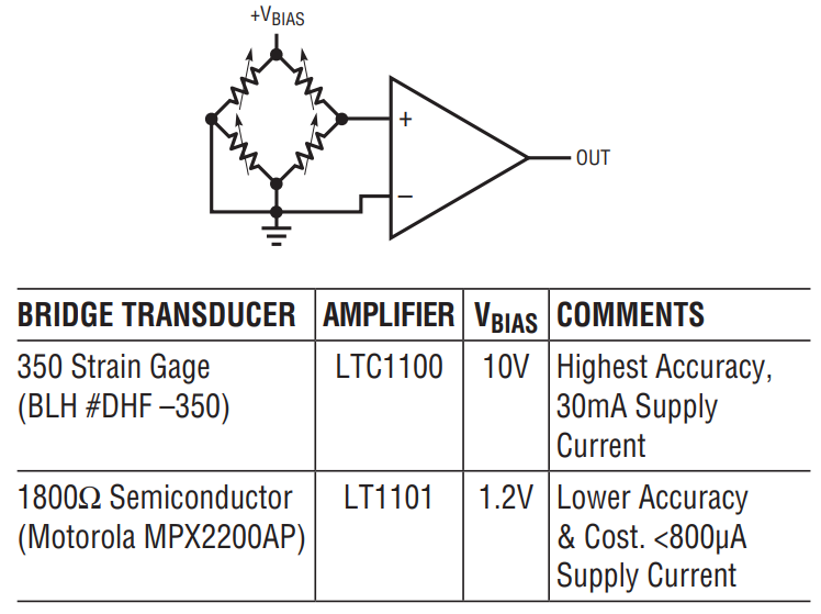
The classic application for these devices is bridge measurement. Accuracy requires low drift, high common mode rejection and gain stability. Figure 3 shows a typical arrangement with the table listing performance features for different bridge transducers and amplifiers.

Figure 3. Characteristics of Some Bridge Transducer Amplifier Combinations.
Bridge measurement is not the only use for these devices. They are also useful as general purpose circuit components, in similar fashion to the ubiquitous op amp. Figure 4 shows a voltage controlled current source with load and control voltage referred to ground. This simple, powerful circuit produces output current in strict accordance with the sign and magnitude of the control voltage. The circuit’s accuracy and stability are almost entirely dependent upon resistor R. A1, biased by VIN, drives current through R (in this case 10Ω) and the load. A2, sensing differentially across R, closes a loop back to A1. The load current is constant because A1’s loop forces a fixed voltage across R. The 10k to 0.5µF combination sets rolloff, and the configuration is stable. Figure 5 shows dynamic response. Trace A is the voltage control input while trace B is the output current. Response is clean, with no slew residue or aberrations.

Figure 4. Voltage Programmable Current Source is Simple and Precise.

Figure 5. Dynamic Response of the Current Source.
A final circuit, Figure 6, combines the current source and a platinum RTD bridge to form a complete high accuracy thermometer. A1A and A2 will be recognized as a form of Figure 4’s current source. The ground referred RTD sits in a bridge composed of the current drive and the LT1009 biased resistor string. The current drive allows the voltage across the RTD to vary directly with its temperature induced resistance shift. The difference between this potential and that of the opposing bridge leg forms the bridge output. The RTD’s constant current drive forces the voltage across it to vary with its resistance, which has a nearly linear positive temperature coefficient. The non-linearity could cause several degrees of error over the circuits 0°C to 400°C operating range. The bridges output is fed to instrumentation amplifier A3, which provides differential gain while simultaneously supplying non-linearity correction. The correction is implemented by feeding a portion of A3’s output back to A1’s input via the 10k to 250k divider. This causes the current supplied to Rp to slightly shift with its operating point, compensating sensor non-linearity to within ±0.05°C. A1B, providing additional scaled gain furnishes the circuit output. To calibrate this circuit, follow the procedure given in Figure 6.

Figure 6. Linearized Platinum RTD Bridge. Feedback to Bridge from A3 Linearizes the Circuit.
Details of these and other instrumentation amplifier circuits may be found in LTC Application Note 43, “Bridge Circuits – Marrying Gain and Balances."
