AN-0997: Ping-Pong Configuration Guide for ADM1062 to ADM1069 Devices
Introduction
The ADM1062 to ADM1069 Super Sequencers® are configurable supervisory/sequencing devices that offer a single-chip solution for supply monitoring and sequencing in multiplesupply systems.
The ADM1062 to ADM1067 devices are capable of monitoring up to 10 input rails (VH, VP1 to VP4, and VX1 to VX5). Both the ADM1068 and ADM1069 can monitor up to eight input rails (VH, VP1 to VP3, and VX1 to VX4). Two internal programmable comparators are connected to each input rail to enable both undervoltage and overvoltage trip with ±1% tripping accuracy at allowable operational voltages and across the entire operational temperature range. With powerful 63-state sequencing engines (SE), the ADM1062 to ADM1069 devices are ideal for applications such as complex multiple input/output sequencing to power-up and power-down supplies.
For some applications, the number of the input rails exceeds the number of input pins on a single device. In these cases, multiple devices can be linked together to cooperate and to form a more powerful Super Sequencer pack with a combined number of inputs, outputs, and states on the sequencing engine. A simple configuration allows devices to be able to hand off control of the sequencing process among them on request, minimize the number of physical links needed for communicating between devices, and at the same time maintain fast system fault response. One such configuration called the ping-pong configuration lets devices exchange control of the sequencing process by transmitting pulse signals forward and backwards between them like a ping-pong ball.
This application note explains the concept and implementation of the ping-pong configuration.
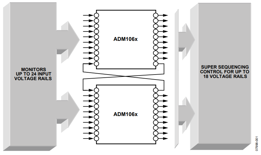
Figure 1. Powerful Cascadability Configuration of the ADM1062 to ADM1069 Devices.
Ping-pong Configuration Concept
The ping-pong configuration is designed for users who require a complex sequencing operation over a number of rails that exceeds the handling capability of a single device.
The concept of the ping-pong configuration is to use pulse signals generated by the sequencing engine (SE) to establish communications among devices to enable a cooperative style sequencing process operation, in which the sequencing control upper hand can be exchanged freely among devices. These pulse signals are used for sequencing control hand-off and fault status indication. To hand off one device to another, a typical sequence consists of the following steps (see Figure 2):
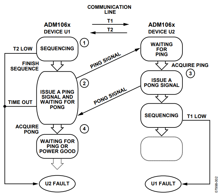
Figure 2. Ping-Pong Sequence Concept.
- U1 sequences, U2 waits for the ping signal.
- U1 stops sequencing and sends a ping signal to U2.
- U2 receives the signal, sends back a pong signal as an acknowledgement, and starts to sequence.
- U1 receives the acknowledgement signal from U2 and then either keeps waiting for the ping signal for further sequencing control exchange or enters a power-good state if all sequencing requirements are done, in which case it can also wait for signals/conditions to start power-down sequencing.
The sequencing control can be handed off from U2 back to U1 using the same principles.
The process stops when all sequences on both devices finish and both devices reach a power-good state. If necessary, the SE could continue for power-down sequencing.
The system is designed to achieve fast fault response. In the case that a fault occurs during the process, all devices in the system quickly enter their designated fault states, which are predefined by their SE. Details of the fault detecting mechanism are explained in the Fast Fault Response section.
Some advantages of the ping-pong configuration are:
- Simple hardware configuration; only one input and one output pin is used on each device. The input pin can even be shared with other voltage input rails (see the Alternative Input Rail Setup section).
- Fast system fault response, deadlock proof.
- Multiple device configuration is possible without the need of additional input/output pins.
Two Device Configuration
Device Setup
An example of basic two device ping-pong configuration is discussed in detail in this section.
Figure 3 shows how two devices are connected. Select one input pin and one output pin on each device for ping-pong signal communication. Two lines, T1 and T2, connect U1 and U2 together. Each selected output pin connects to the selected input pin on the other device. Any of the input and output rails on the device can be chosen for this application, although the use of a VXx pin configured as digital input is recommended.
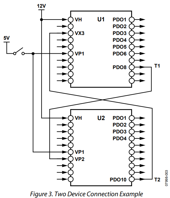
Figure 3. Two Device Connection Example.
In this example, the input and output pins are randomly selected. Input Pin VX3 and Output Pin PDO8 of U1 and Input Pin VP2 and Output Pin PDO10 of U2 are used.
The graphic user interface (GUI) provided in the ADM1062 to ADM1069 evaluation kits can be used to configure the characteristics of the input and output pins. Use the GUI to set the ping-pong communication outputs of the device (in this case PDO8 for U1 and PDO10 for U2) as controlled by SE and Strong pull-up to VDDCAP. In this example, the remainder of the outputs for both devices are setup in the same way for demonstration purposes. VX3 of U1 and VP2 of U2 are set up as digital inputs to detect the output voltage of each other’s ping-pong output signal, and the value of the threshold is set according to the corresponding output level. For example, Output PDO8 of U1 is set to pull up to its VDDCAP pin with typical voltage of 4.75 V and then depends on the state in the SE; the output voltage of PDO8 is either 4.75 V or 0 V. To detect the difference, set the VP2 input of U2 to the undervoltage fault detector with a threshold of around 2.5 V.
VXx inputs are recommended for this configuration so that the UV/OV comparators for this input can be used to monitor other input rails and act as warring detectors (see the ADM1062 to ADM1069 data sheets for more details). If using VXx as a digital input for ping-pong configuration, the detection mode is required to be set as level detect rather than edge detect. See the device evaluation kit data sheet for more details about settings.
Other inputs used in this example are the VH and VP1 pins on both devices. The VH pins are connected to the 12 V rail to supply power to the devices, and the VP1 pins are pulled up to a 5 V rail through a common switch, which is used to initiate the ping-pong demonstration.A summary of pin usage from this example is shown in Table 1.
| Device | Ping-Pong | Demo Initiation | Power | Demo |
| U1 | VX3, PDO8 | VP1 | VH | PDO1 to PDO6 |
| U2 | VP2, PDO10 | VP1 | VH | PDO1 to PDO4 |
In this example, the two devices are set to perform a sequencing control hand-off process using ping-pong signals a few times before they reach their power-good states.
The hardware configuration is relatively simple. The ping-pong technique is achieved mostly through the software configuration. The programmable SE on the device plays a major role in this application.
Before starting with the SE, design the system’s timing diagram. This is a overview of the timing design of the states required for ping-pong communication, which is one of the most important steps for ping-pong configuration design.
The timing diagram designed for this example is shown in Figure 4.
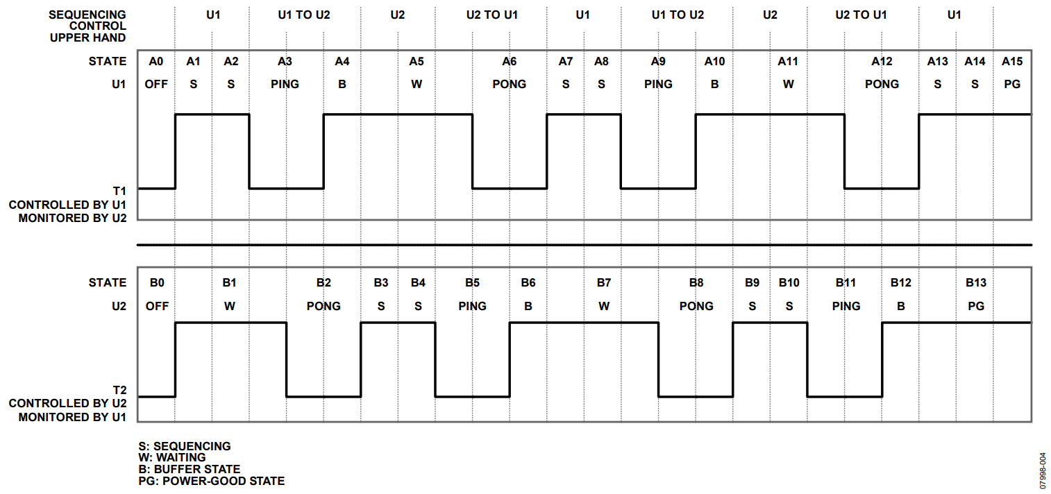
Figure 4. System Timing Diagram.
Figure 4 is an overview of the timing diagram for the entire system. It shows the status (high or low) of the T1 and T2 communication lines, relative to the states in the SE for both devices. Note that T1 represents the status of U1’s PDO8 output, which is controlled by the SE in U1 and monitored by U2 on its VP2 input. T2 represents the status of U2’s PDO10 output, which is controlled by the SE in U2 and monitored by U1 on its VX3 input. Keep in mind that the status of the output cannot change within one state (for example, T1 cannot go from high to low in State A3), it can only change if the state is changed.
Note that the devices can only monitor each other’s status by the other device’s communication output. For example, U1 can only determine the status of U2 by monitoring T2. In other words, U1 controls T1 and monitors T2, and U2 controls T2 and monitors T1.
The following sections examine each section of Figure 4 in more detail.
The following paragraphs explain in detail how the ping-pong sequencing hand-off works.
Figure 5 shows an enlarged version of the left most part of the timing diagram in Figure 4. This is where the first sequencing hand-off takes place.
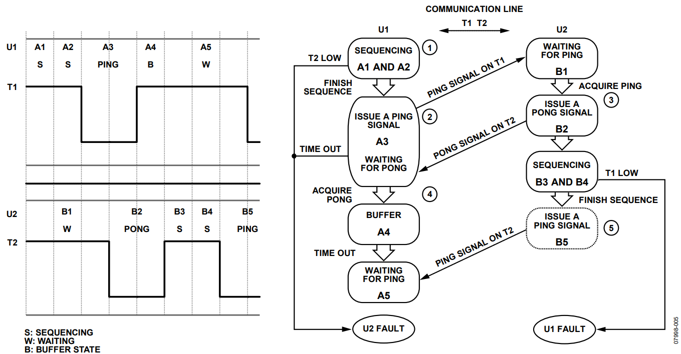
Figure 5. Detailed Graphical Illustration of the Ping-Pong Sequence.
In Figure 5, the following sequence takes place:
- U1 performs the normal sequencing operation programmed in SE; the sequencing can use several states. In this example, two states (A1 and A2) are used. To simulate sequencing operation, each state lasts 400 ms, drives an additional output high, and starts from PDO1. U1 keeps T1 (the PDO8 output) high in these states. (The 400 ms is used in this example for easy visual inspection. If the output is connected to LEDs, this value can be configured freely.) See Table 2 for details about SE configuration. In the meantime, U2 is idling with T2 high (the PDO10 output) and monitoring T1. U2 waits for T1 to go low (and stay low) for 1 ms before moving to the next state. All the instances of 1 ms and 2 ms time duration used for pingpong process in this example are chosen for demonstration purposes. Users can set the time to 0.1 ms and 0.2 ms for faster fault response.<
- U1 finishes its sequencing operation and is ready to hand over the sequencing control upper hand to U2. U1 enters State A3, where it pulls T1 low and sends a ping signal to trigger U2 acting as a wake-up call.
- After T1 goes low for 1 ms, U2 in State B1 meets the condition and moves to the next state, B2, in which it pulls T2 low and stays for 2 ms (timeout for 2 ms) before moving to next state, B3. This acts as the pong signal or an acknowledgement to U1’s ping signal.
- One of the exit conditions in State A3 is for T2 to go low (and stay low) for 1 ms. (There is another timeout exit condition designed for fault proof is explained in the Fast Fault Response section.) This is effectively the pong signal from U2. Once this condition is met, U1 enters the next state, A4, where it pulls T1 back to high and stays there for 1 ms (TIMEOUT for 1 ms) before entering the next state. State A4 is called the buffer state and its purpose is explained in the Timing and Buffer section. At this point, the sequencing handover from U1 to U2 is over, and U1 enters State A5, waiting for a ping signal from U2. State A5 of U1 effectively acts as State B1 for U2. U2 enters State B3 and starts its sequencing operation following the programs in its SE. State B3 and State B4 play the same role as State A1 and State A2.
- The sequencing control hand over takes place again from U2 to U1 after State B4, in the same fashion as previously described in Step 2.
| State | Output | Sequence | Timeout | Monitor |
| Reserved | ||||
| A0 | 0000000000 00 | If VP1 (VP1) is OK GOTO A1 after 40 ms | ||
| A1 | 0000000001 00 | After 400 ms GOTO A2 | XXXXX11XXXX GOTO fault | |
| A2 | 0000000011 00 | If T2 (VP2) is OK GOTO A3 after 400 ms | If T2 (VP2) is not OK after 40 ms GOTO fault | XXXXX11XXXX GOTO fault |
| A3 | 1000000011 00 | If T2 (VP2) is fault GOTO A4 after 1 ms | If T2 (VP2) is not fault after 10 ms GOTO fault | |
| A4 | 1000000011 00 | After 1 ms GOTO A5 | ||
| A5 | 1000000011 00 | If T2 (VP2) is fault GOTO A6 after 1 ms | XXXXX1XXXXX GOTO fault | |
| A6 | 0000000011 00 | After 2 ms GOTO A7 | XXXXX1XXXXX GOTO fault | |
| A7 | 1000000111 00 | After 400 ms GOTO A8 | XXXXX11XXXX GOTO fault | |
| A8 | 1000001111 00 | After 400 ms GOTO A9 | XXXXX11XXXX GOTO fault | |
| A9 | 0000001111 00 | If T2 (VP2) is fault GOTO A10 after 1 ms | If T2 (VP2) is not fault after 40 ms GOTO fault | XXXXX1XXXXX GOTO fault |
| A10 | 1000001111 00 | After 1 ms GOTO A11 | XXXXX1XXXXX GOTO fault | |
| A11 | 1000001111 00 | If T2 (VP2) is fault GOTO A12 after 1 ms | XXXXX1XXXXX GOTO fault | |
| A12 | 0000001111 00 | After 2 ms GOTO A13 | ||
| A13 | 1000011111 00 | After 400 ms GOTO A14 | XXXXX11XXXX GOTO fault | |
| A14 | 1000111111 00 | After 400 ms GOTO A15 | XXXXX11XXXX GOTO fault | |
| A15 | 1000111111 00 | XXXXX11XXXX GOTO fault | ||
| Fault | 0000000000 00 | If VP1 (VP1) is fault GOTO A0 after 0 ms |
Timing and Buffer
In State A3, the exit condition requires that T2 go low for 1 ms. This raises the question: why does the pong generated by State B3 last 2 ms?
The answer has to do with the timing specification of the device. The sequencing engine of the device has an accuracy of 10%. This means the time set and detected by the SE could vary by ±10%. As shown in Figure 6, if the SE sets B2 to run for 1 ms, the actual time varies from device to device by ±0.1 ms. In Worst-Case Scenario 1, the state ends up running for 0.9 ms or 1.1 ms. This ±10% timing accuracy also applies to the timing detection function of the device. Thus, in Worst-Case Scenario 2 where B2 is designed to last only 1 ms, the actual State B2 only lasts 0.9 ms. This means T2 goes low for 0.9 ms acting as a pong signal. Meanwhile A3 is looking for a 1.1 ms (worst-case) pong signal. In this case, A3 does not recognize the pong signal (as it is 0.2 ms too short) and goes to a fault state instead (see the Fast Fault Response section).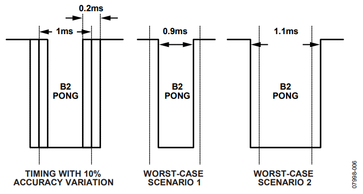
Figure 6. Timing Accuracy Diagram.
Therefore, the reason for having B2 last 2 ms is to overcome the timing inaccuracies and allow sufficient time for A3 to detect the pong signal.
The timing accuracy consideration also leads to the usage of State A4 in this design. The actual state timing in the device may vary by ±10%. If State A4 does not exist in the configuration in the SE, U1 exits A3 and goes to A5 after T2 goes low for 1 ms, that is, U2 enters B2 for 1 ms (see Figure 7). A5 is a waiting state similar to B1 and is waiting for a ping signal from U2, that is, for T2 to go low for 1 ms. Thus, in the worst-case scenario of the ±10% state timing variation, SE in U1 moves from A3 to A5 only 0.9 ms after U2 enters B2. If B2 lasts for 2.2 ms (worst-case scenario), this results in U1 in State A5 detecting T2 low for 1.3 ms (see the shaded area in Figure 7), and mistaking it for a ping signal from U2 and entering the next state, causing it to wake up and start sequencing unexpectedly.
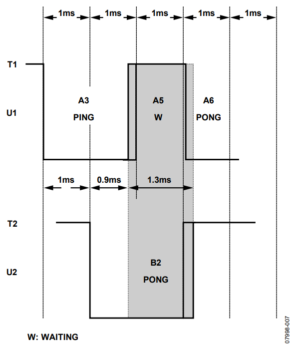
Figure 7. Worst-Case Scenario Without Buffer.
Adding State A4, which is a time buffer state, generates a 1 ms delay between two states. In this case, having A4 placed between A3 and A5, even with the worst-case scenario (A3 exits 0.9 ms after U2 enters B2, B2 lasts 2.2 ms, and A4 lasts only 0.9 ms), U1 in State A5 still can only detect T2 if it goes low for 0.4 ms (see the shaded area in Figure 8). Thus, it does not react to it as to a ping signal.
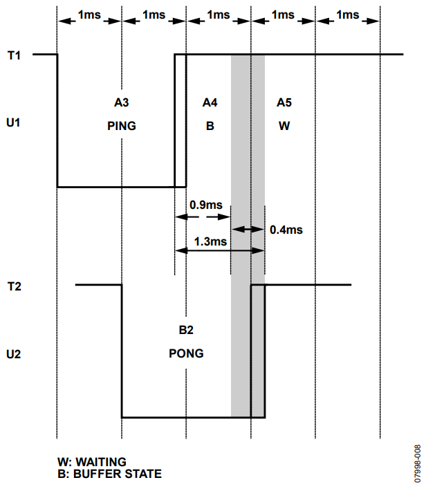
Figure 8. Worst-Case Scenario With Buffer.
Fast Fault Response
It is critical that all devices sequence properly. If a fault condition appears on one device, the other device is able to acknowledge it and respond quickly. A poor case of fault proof design results in one device being in a faulty condition and the other device continuing to sequence the power rail or getting stuck in a dead lock situation waiting for signals from other devices without knowing they are in a faulty condition. To prevent this from happening, the SE needs to be carefully programmed to cover all possible faulty situations.
One of the great advantages of using the ping-pong configuration is its ability to respond quickly when a fault occurs. Figure 9 shows the fault monitoring techniques employed in different states. The ADM1062 to ADM1069 devices are equipped with many mechanisms to detect input fault. In the case that a device detects a fault condition by itself, it should go to a predefined fault state in its SE where it pulls its ping-pong output low.
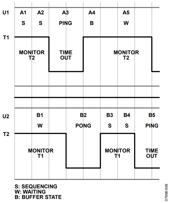
Figure 9. Fault Proof in Each Type of State.
For the ping-pong configuration setup in all sequencing states (for example, states A1, A2, B3, and B4), devices should monitor the ping-pong communication line for fault states. From timing diagram design, under normal operation when one device is in a sequencing state, the other device should keep its ping-pong output high (see Figure 4). A low on this output indicates a fault occurred on this device. For example, in State B3, U2 should monitor T1, and if T1goes low, this indicates a fault status on U1. The warning functions in these states can be used for monitoring the communication line.
In states like A3 and B5 where a device generates a ping signal and is waiting for a pong signal, the device should acknowledge a fault condition if the other device did not respond after a certain amount of (user-defined) time. To do this, this state needs to use the timeout function for fault detection. For example, in A3, if T2 is low for 1 ms, go to A4, and timeout for 10 ms to go to a fault state. In this case, if U2 did not respond to a ping with a pong (pulls T2 low) after 10 ms, U1 goes to a fault state.
In a state like B1 and A5, where the device is waiting for a ping signal, there is no need to set up any fault proof mechanics, as its exit condition is for T1 to go low for 1 ms. In this case, if U1 detects a fault condition in A1 or A2 or a timeout in A3, U1 enters its fault states, where T1 goes low. After 1 ms, U2 enters to B2 where it stays for 2 ms before entering B3. In B3, U2 detects that T1 is still low and goes to its fault state.
According to this design, if condition appears on one device, the other device is able to react within less than a millisecond (if using 0.1 ms and 0.2 ms for ping-pong communication state time). Thus, the design achieves fast fault response.
Alternative Initial States Setup
A point worth noting from the previous design example is that the two devices need to start sequencing at the same time. For example, U1 enters A1 at the same time U2 enters B1, otherwise a fault condition could be triggered due to the fault monitoring mechanism mentioned previously. In this example, this is achieved by having VP1 inputs on both devices connected together through a common switch. However, this can be difficult to achieve in common practice. The best suggestion is to use the procedure in the following two paragraphs:
Alternatively, U1 can start sequencing with T1 low, and to initiate the very first sequence handover, it pulls T1 high, as shown in Figure 10. See Table 2 for details about SE configuration. For U2 to respond to this, change State B1’s exit condition to: if T1 is high for 1 ms. In this case, the start timing is not as critical as in the previous example. This works as long as U2 is in State B1 when the first ping took place.
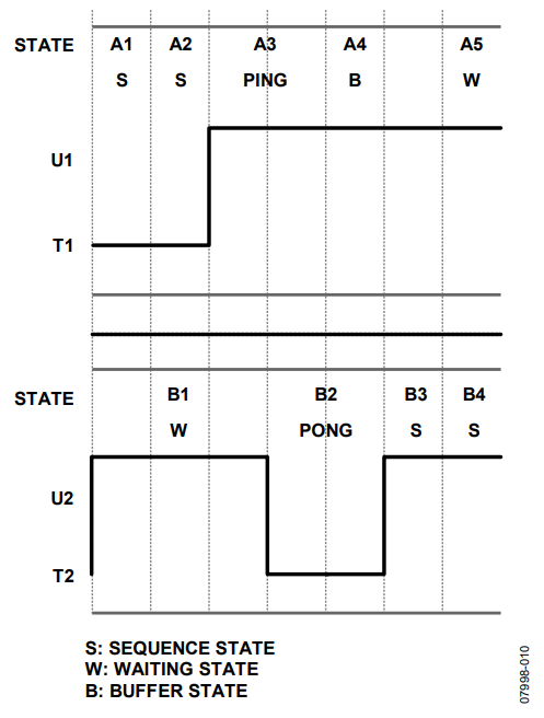
Figure 10. Alternative Kick Off States Setup.
Note that this approach only needs to be used for issuing/ detecting the first ping signal. The remainder of the timing diagram design should be similar to the diagram shown in Figure 4.
Alternative Input Rail Setup
By employing a certain hardware architecture, it is possible to enable the ping-pong signal transmission without dedicating one of the input rails on each device. Instead, certain input rails can be used in conjunction with the communication line to provide both voltage monitoring and ping-pong signal receiving functions. This allows up to a 24-rail monitoring capability by using two ADM1066 devices. This architecture would apply to the device that has one of its input rails connected to a constant voltage source throughout the entire sequencing operation. This could be an input voltage that initiates the sequencing process and stays constant afterward. For example, VP1 in Figure 3 from the previous example, may be the power supply voltage source, commonly the VH pin.
Figure 11 shows an example of such architecture. It is a modified version of the original devices connection setup. Here, instead of using VX3 for ping-pong signal transmission only, the VH pin (which is previously used for the device power supply) is now used for both power supply and ping-pong signal transmission. The idea behind this is to use a temporary voltage drop on the VH pin as the ping-pong communication line low signal. This voltage drop only lasts a short period and is still high enough to power the device. In the event a real VH fault occurs, the device is able to detect it in the next state.
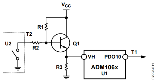
Figure 11. Alternative Input Rail Setup.
In this setup, the ping-pong output on the other device, U2 (which controls T2) is set to be an open-drain type controlled by the SE (instead of pulling up to VDDCAP as in the previous example).
This architecture requires four external components: R1, R2, R3, and Q1. Three resistors (R1, R2, and R3) form two voltage divider circuits and an NPN transistor (Q1) acts as a switch. The reason for using a transistor here is to provide a clean power supply with low impedance thus providing the current needed for the device.
When U2 sets its ping-pong output to logic high (output open), no current flows through R2. The base voltage on Q1 is equal to VCC, and Q1 turns on. The higher-level voltage VHHIGH on the VH pin of U1 equals VCC – 0.7 V, where 0.7 V is the VBE on Q1. Once the ping-pong output on U2 goes low (output drain), R1 and R2 form a voltage divider making the base voltage on Q1 equal to VCC × R2/(R1 + R1), thus making the lower-level voltage VHLOW on the VH pin equal to VCC × R2/(R1 + R1) − 0.7 V. Note that VHLO should be high enough to maintain normal device operation.
The value of the VH pin UV fault threshold voltage, VHTH, is chosen between VHLOW and VHHIGH.
VCC × R2/(R1 + R2) − 0.7 V < VHTH < VCC – 0.7 V
and
VCC × R2/(R1 + R2) − 0.7 V > required supply voltage
In this case, a low ping-pong signal sent by U2 is recognized as an undervoltage fault on the VH pin by U1 and can be used in similar fashion as the VX3 pin shown in Figure 3. The VH pin on U1 now has the ability to acknowledge the logic difference of T2, thus pulse signals can be transmitted between devices. Remember, only ping and pong states require the VH to go low, thus in other sequencing states U1 should keep monitoring the voltage level of the VH pin in case a real voltage fault occurs.
Application Example
VCC, a 12 V rail, sets the undervoltage fault threshold, VHTH, to 10.5 V. Below this voltage, a fault is generated. This also meets the requirement of VHTH < VCC – 0.7 V. Set this value in the software’s input configuration section for the VH pin under the voltage threshold.
Choose the value for the resistors (R2 and R3). The values for R2 and R3 determine the current flow through the voltage divider. Increasing their value decreases the current leakage. Set them both to 100 kΩ. Now, choose a voltage for VHLOW. Set it for 10 V, high enough to maintain power to devices and lower than the VHTH. Now,
VCC × R2/(R1 + R2) − 0.7 V = 10 V
where
VCC = 12 V.
R2 = 100 K.
Then calculate the value for R1 approximately equal to 12 kΩ.
| State | Output | Sequence | Timeout | Monitor |
| Reserved | ||||
| B0 | 0000000000 00 | If VP1 (VP1) is OK GOTO B1 after 0 ms | ||
| B1 | 1000000000 00 | If T1 (VP2) is OK GOTO B2 after 1 ms | XXXXX1XXXXX GOTO fault | |
| B2 | 0000000000 00 | After 2 ms GOTO B3 | XXXXX1XXXXX GOTO fault | |
| B3 | 1000000001 00 | After 400 ms GOTO B4 | XXXXX11XXXX GOTO fault | |
| B4 | 1000000011 00 | After 400 ms GOTO B5 | XXXXX11XXXX GOTO fault | |
| B5 | 0000000011 00 | If T1 (VP2) is fault GOTO B6 after 1 ms | If T1 (VP2) is not fault after 40 ms GOTO fault | XXXXX1XXXXX GOTO fault |
| B6 | 1000000011 00 | After 1 ms GOTO B7 | XXXXX1XXXXX GOTO fault | |
| B7 | 1000000011 00 | If T1 (VP2) is fault GOTO B8 after 1 ms | XXXXX1XXXXX GOTO fault | |
| B8 | 0000000011 00 | After 2 ms GOTO B9 | XXXXX1XXXXX GOTO fault | |
| B9 | 1000000111 00 | After 400 ms GOTO B10 | XXXXX11XXXX GOTO fault | |
| B10 | 1000001111 00 | After 400 ms GOTO B11 | XXXXX11XXXX GOTO fault | |
| B11 | 0000001111 00 | If T1 (VP2) is fault GOTO B12 after 1 ms | If T1 (VP2) is not fault after 40 ms GOTO fault | XXXXX1XXXXX GOTO fault |
| B12 | 1000001111 00 | After 1 ms GOTO B13 | XXXXX1XXXXX GOTO fault | |
| B13 | 1000001111 00 | If T1 (VP2) is fault GOTO fault after 100 ms | XXXXX1XXXXX GOTO fault | |
| Fault | 0000000000 00 | If VP1 (VP1) is fault GOTO B0 after 0 ms |
