Ultra Low Power Microcontroller Module Opens New Doors for Engineers—Part 2: Configuring Eclipse
Ultra Low Power Microcontroller Module Opens New Doors for Engineers—Part 2: Configuring Eclipse
Apr 24 2025
Read other articles in this series.
Abstract
This article continues the introduction of an ultra low power, feature rich microcontroller module and explains how to program and debug it using popular, free of charge tools. Unlike many other high end microcontroller modules, this one is available in a DIP footprint, allowing easy prototyping for professional engineers and hobbyists alike. While Part 1 describes how to create a project in Eclipse, Part 2 describes how to configure Eclipse to work with the PICO.
Reconfiguring Eclipse to Work with the PICO Hardware
The project created in Part 1was designed around the MAX32625EVKIThardware, which is different from the PICO hardware, so the file describing the hardware on the EV kit needs to be changed to reflect the hardware on the PICO. The original boards.c file is stored in:
C:\Maxim\Firmware\MAX32625\Libraries\Boards\EvKit_V1\ Source
and the new boards.c file for the PICO is stored in the zip file, which can be downloaded using the link at the end of this article. Copy the whole Boards directory from the zip file into the directory where the main program is saved as shown in Figure 1. This directory describes the components included in the PICO PCB.


The PICO contains a bootloader to enable the program to be run. The bootloader also allows the binary file to be loaded using drag and drop. Eclipse will overwrite this bootloader if the program is loaded into the MAX32625 with the default settings. The linker file, called max32625.ld, brings all the programs together into a binary file to be loaded into the host microcontroller. It also determines which part of memory the program is loaded into and this needs to be modified so as not to overwrite the bootloader. The modified linker file is contained in the downloaded zip file.
Copy the linker file to the project directory as shown in Figure 1.
The Makefile, stored in the project directory, tells the compiler where to find the linker file and Boards directory, so it needs to be edited to point to the new location of the modified linker file and Boards directory. Copy the new Makefile from the zip file into the project directory as shown in Figure 1, overwriting the original.
Inside the new Boards directory, a modified board.c file (in the EvKit_V1\Source directory) can be found, which describes the connections to the LEDs and pushbuttons on the PICO. It is easy to see how this is constructed by comparing the code in Figure 2 with the PICO schematic in Figure 3.


The boards.c file has also been extensively modified to allow the PICO to print data to a terminal program, like Tera Term, which can prove invaluable in the debug process. If the print function is used, configure the terminal program to communicate at a baud rate of 115200 as shown in Figure 4.


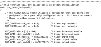
The bootloader can leave some peripherals in a partially configured state and there is more code in board.c to reset them during initialization as shown in Figure 5.

Finally, the PICO uses a different power management IC from the EV kit. However, the PICO’s power management IC does not need programming as it runs with its default settings, so the lines of code that configure it have been deleted from the new board.c file.
Building the Final Project
The zip file contains a sample program, main.c in the Template folder, that detects when the PICO’s pushbutton has been depressed, then flashes the RGB LED on and off, sends out 2 bytes of data via the SPI port, then sends out one byte of data via the UART, then prints Hello from the PICO on a terminal program. Copy this program into the project directory, overwriting the original. The main.c code has been copied from the many sample programs in the MAX32625 project directories as seen in the code’s comments. This should give the user a head start in creating the final application code.
Build the project by clicking on the Hammer symbol as shown in Figure 6. If more than one project is open in Eclipse, hovering over the Hammer symbol tells the user which project is about to be built.


The binary file should now be in the build directory of the project’s directory as shown in Figure 7.

At this point, it is wise to add the build directory to the Windows Explorer Quick Access menu. This will prove useful when programming the PICO. Right click over the build directory and select Pin to Quick access and the directory will appear on the left side of the Windows Explorer menu, under Quick access.
Loading a Binary File
It is important to note that the programming cable is only used to debug the target PICO and to reprogram the part if the bootloader has been overwritten. Loading the binary file does not require the use of the programming cable and is a simple drag and drop process.
While holding down the button on the PICO, plug it into the USB port. The PICO should appear as a new drive, labeled MAINTENANCE as shown in Figure 8.


Drag the binary file to the MAINTENANCE drive. Once the file has loaded onto the PICO, the MAINTENANCE drive should disappear, the PICO will reboot, and the program will start to run on the PICO.
In the early stages of code development, it is unlikely that the code will run as predicted, if at all. If the software on the target PICO needs to be debugged (including stepping through the code or halting at breakpoints), the second programmer PICO needs to be programmed with the interface software to enable it to be connected between the PC and the target PICO. This programmer PICO issues instructions to the target PICO to start and stop the target’s execution, enabling Eclipse to examine the registers.
To configure the second programmer PICO, navigate to the binary file in the DAPLink Interface Binary directory in the zip file. Disconnect the second programmer PICO from the USB port then hold down the button on the programmer PICO while plugging it back into the USB port. As previously discussed, a drive called MAINTENANCE should appear. Drag the binary file (max32625_max32625pico_if_crc.bin) from the DAPLink Interface Binary directory to the MAINTENANCE drive. This will configure the programmer PICO with the interface software and allow single stepping of the target code using Eclipse. The MAINTENANCE drive should disappear, the programmer PICO will reboot, and a drive called DAPLINK will appear. At this stage, it is worth connecting the programming cable to the programmer PICO to distinguish it from the target PICO.
How to Debug the Target Code
With the programming cable connected to the 10-way plug on the programmer PICO, press the pogo connector on the other end to the pads on the rear of the PICO, ensuring the alignment pins slot into the holes on the PICO as shown in Figure 9.


Hover the mouse over the debug icon in Eclipse as shown in Figure 10 to ensure the correct project is to be debugged. The name of the current project should appear.


Click the debug icon, while keeping the pogo connector attached to the PICO. The program will compile, then pause at the start of the code. Hitting F8 on the keyboard will start the debug process.
Double clicking over the code’s line numbers inside Eclipse allows the user to insert breakpoints.
The user can now debug the code. Registers can be examined by selecting:
Window > Show View > Other…
from the Eclipse menu, then selecting the desired views by expanding the Debug folder.
Once it has been established that the code works, this project can be saved to act as a template for future projects.
How to Recover a Broken PICO
The PICO comes with a preinstalled bootloader that enables drag and drop programming. When the PICO is plugged in, if neither the MAINTENANCE nor DAPLINK drives appear, then it is likely that the bootloader has been overwritten. The bootloader can be recovered using the following steps.
- Plug in the programmer PICO and see that a DAPLINK drive is created.
- Plug in the broken PICO.
- Hold the sprung connectors of the programming cable against the pads on the rear of the broken PICO, ensuring the alignment pins slot into the holes on the PICO.
- Navigate to the Bootloader Binary directory and drag the bootloader file (max32625pico_bl.bin) to the DAPLINK drive. It is important to note that the binary is copied to the drive created by the programmer PICO and not the target PICO. The programmer PICO is being used as a conduit to route the binary file to the target PICO via the programming cable.
- The user should now be able to see the MAINTENANCE drive when the repaired PICO is plugged in while holding down the button on the PICO.
- Unplug the programmer PICO.
How to Erase Files in the PICO
Should it be necessary to completely erase the contents of the PICO, follow the steps:
- Plug the programmer PICO into a USB port. It will create a drive called DAPLINK.
- Plug the PICO that needs to be erased into another USB port.
- Hold the sprung connectors of the programming cable against the pads on the rear of the PICO to be erased.
- Navigate to the erase.act file in the Erase File directory in the zip file.
- Drag this file to the DAPLINK drive. The programmer PICO is being used as a conduit to route the erase file to the target PICO via the programming cable.
- This will erase the target PICO.
Conclusion
This could be the start of a good friendship with the PICO. It provides a great, low cost platform to enable the user to develop with an extremely powerful yet ultra low power Arm® microcontroller. This article gives a complete guide on how to use free of charge development tools to program and debug the PICO. Once users have been successful with one project, this project can be used as a template for future developments with minimal extra effort. Finally, the 8-bit DIP world can be left behind and the users can progress into the world of 32-bit microcontrollers while still being able to prototype with a manageable package.
Download the software files here: https://www.analog.com/media/en/software/software-configuration/eclipse-configuration.zip
Acknowledgments
I owe a debt of gratitude to ADI’s microcontroller support team for helping me write this article and for their extensive modification of the configuration files.
About the Authors
Simon Bramble graduated from Brunel University in London in 1991 with a degree in electrical engineering and electronics, specializing in analog electronics and power. He has spent his career in analog electronics and
Related to this Article
Products
NOT RECOMMENDED FOR NEW DESIGNS
Ultra-Low-Power Arm Cortex-M4 with FPU-Based Microcontroller (MCU) with 512KB Flash and 160KB SRAM
Evaluation Kit for the MAX32625 and MAX32626
Evaluation Kit for the MAX32625/MAX14750
Resources
Software Development Kit
Secure Software Download


