Abstract
This application note demonstrates how to configure the MAXQ2000 microcontroller for a simple voltmeter application. The application uses the MAXQ2000 Evaluation Kit, which includes a 4½-segment LCD display and a MAX1407 data acquisition system (DAS), plus a pair of external resistors. The MAXQ2000 voltmeter will measure and display any voltage from 0 to 10V.
Introduction
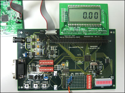
This application note describes how to setup the MAXQ2000 Evaluation Kit (EV kit) as a simple voltmeter.
This EV kit contains the MAXQ2000-RAX microcontroller, The MAXQ2000 does not have an onboard ADC, so the EV kit is equipped with a MAX1407 data acquisition system (DAS) to perform the analog-to-digital conversions. The EV kit already has a 4½-segment LCD display. By adding a +5V power supply and an RS-232 cable connected to a PC, the EV kit provides a completely functional voltmeter that will measure 0 to 10V DC.

Figure 1.
Simple Voltmeter Application
The firmware for the voltmeter application is contained in the main.c file, found under the file name an4194_sw.zip, which is available for download. The firmware uses the MAXQ2000's hardware SPI™ interface to communicate with the MAX1407 DAS. The MAXQ2000 will use its hardware LCD controller to display the voltage on the EV kit's LCD.
After reset, the MAXQ2000 initializes its onboard LCD by calling the lcd_init() function. Next the MAX1407 RESET line is pulled low to reset the ADC, and then initialized by calling the max1407_init() function. Once the ADC is initialized, the commands are issued through SPI to configure the internal multiplexer to read the voltage on the IN0 pin and to perform a calibration. After calibration, the MAX1407 is instructed to perform ADC conversion on the IN0 line at a rate of 30 times per second.
The MAX1407's DRDY (Data Ready) line is connected to the MAXQ2000's P6.1 input. This line is high while the MAX1407 is performing its ADC conversion. The line goes low when conversion data is ready to be read by the microprocessor. The conversion data is averaged over 30 samples (in the firmware application) to keep the LCD from displaying a quickly changing value.
The filtered result, i.e., the voltage read by the MAX1407 DAS with 0.01V resolution, is passed to a function called display_voltage(). If the ADC reads a value of 7.89V, for example, it will pass the value "789" to the display_voltage() function. This function displays the integer number properly on the LCD with the decimal point to the right of the 100s digit. If the integer passed is equal to, or greater than MAX_DC_VOLTS, then an error will be displayed as "-E-."
Modifying the MAXQ2000 EV Kit Hardware
The raw input voltage must be conditioned with a divide by 4 before it is connected to the IN0 input of the MAX1407 DAS. This conditioning can be accomplished with a simple resistor-divider (3.00kΩ 1% between the meter's input voltage and IN0 pins, and 1.00kΩ 1% between the IN0 pin and ground). Additionally, you can also use an operational amplifier to buffer (such as a TL084) so the resistor-divider will not load the source.
If there is any chance that the voltage on the IN0 pin can go above +3.3V or below ground, Schottky diodes should be connected between the IN0 pin and the +3.3V supply and ground.
The MAXQ2000-RAX EV kit requires a +5V ±5% power supply. There are numerous sources for this power. Radio Shack(s) stocks it under part number 273-1696. (You will also need a 273-1717 adapter plug to match the jack on the EV kit.)
IAR Embedded Workbench® for MAXQ
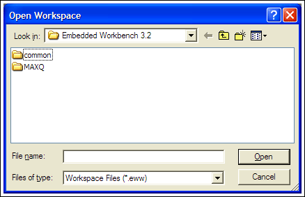
The IAR Embedded Workbench, available for download from the Maxim website, was used to develop this application note. After you install it on your PC, select File then Open Workspace .... You will see the following dialog box:

Figure 2.
Use this dialog box to navigate to the place where you stored the project workspace on your hard drive. Select the voltmeter.eww file and click the Open button. Note that you might receive the message, "The project 'voltmeter' contains the unknown tool 'MAXQEMU'. A backup copy of the original file will be made before the project is loaded." It can be safely ignored for the purposes of this application note.
In the IAR Embedded Workbench select Project then Rebuild All to build all the source code necessary for the voltmeter application. It should compile with no errors or warnings.
Follow the MAXQ2000 EV kit directions and use the ribbon wire header cable to connect the LCD module to the main EV kit board and the MAXQJTAG module. Now with all three EV kit boards connected, the power supplied, and the RS-232 cable connected to your PC, just select Project then Debug. This action will cause the object code to be downloaded to the target MAXQ2000 and will prepare it to execute. Select Debug then Go and you are running the voltmeter application! If nothing is displayed, check DIP switch SW3 and make sure that all switches are in the "on" position.
Conclusion
This simple voltmeter application demonstrates one possible use for the MAXQ2000 microcontroller and its EV kit. The application only required the MAXQ2000 EV kit, a resistor-divider, and an external power supply. The resulting voltmeter measures 0 to 10V DC.
Related to this Article
Products
Low-Power LCD Microcontroller
Low-Power, 16-Bit Multichannel DAS with Internal Reference, 10-Bit DACs, and RTC


