Abstract
The DS2786K was created to make evaluating the DS2786 stand-alone open-circuit voltage (OCV) based fuel gauge easy. The DS2786K data sheet provides information on connecting the hardware and installing the software on a PC. This application note provides a detailed description of terms used in the DS2786K, as well as a step-by-step procedure for getting started using the DS2786 as a stand-alone OCV-based fuel gauge.
Overview of the DS2786
The DS2786 stand-alone OCV-based fuel gauge estimates the available capacity of rechargeable Li+ batteries based on the cell voltage in an open-circuit state following a relaxation period. The open-circuit voltage is used to determine relative cell capacity based on a lookup table stored in the IC. This capability makes accurate capacity information available immediately after a battery pack is inserted. The cell characteristics and application parameters used to calculate relative capacity are stored in on-chip EEPROM.
Setting Up Fuel-Gauge Parameters
Once the DS2786K software is installed and communicating with the DS2786, as described in the DS2786K data sheet, the first step in starting the stand-alone fuel gauge is to load application specific data into the DS2786.
The DS2786 comes preloaded with a "best fit" OCV/remaining capacity curve and standard default parameters. The "best fit" curve was created by characterizing cells of various sizes from various manufacturers. This curve provides a very good open-circuit-voltage profile that will fit most applications. For the purposes of this application note, we will assume a typical application that uses the default parameters.
The required data is stored in Addresses 60h–7Fh and includes the OCV profile of the Li+ cell, as well as the values associated with cell capacity, the thresholds for detecting an open-circuit voltage, and the Configuration and Current-Offset Bias registers. This data can be entered in the DS2786K on the PARAMETERS tab (Figure 1); the DS2786K automatically converts the values entered to the appropriate values that are actually stored in memory. The arrows in Figure 1 point to the various labels that are described in the following sections.
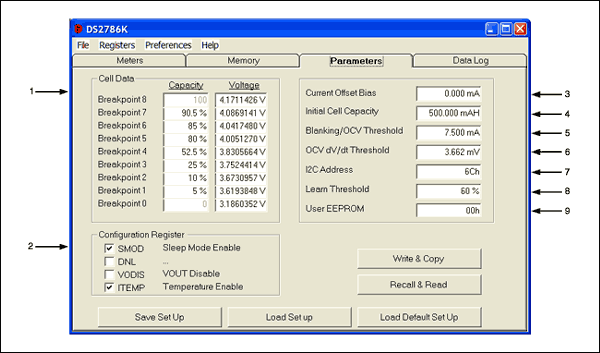
Figure 1. Illustrates the PARAMETERS tab of the DS2786K. The arrows point to the various parameters that are described in this application note.
- Cell Data
The DS2786 comes preloaded with a "best fit" curve for a typical Li+ cell (Figure 2). This curve is an 8-segment, piece-wise linear approximation of the remaining relative capacity versus the open-circuit voltage of the cell. Cell Data is shown on the PARAMETERS tab as breakpoints consisting of remaining cell capacity (Capacity) and OCV (Voltage) pairs. Capacity points are stored in 0.5% steps, and Voltage points are stored in 1.22mV steps. The first and last data points of the Capacity column are fixed at 0% and 100%.
If the user desires to use an OCV profile for the exact cell being used, simply enter the new Capacity and Voltage breakpoints into the text boxes and write the new values to the DS2786 as described below in the "Accessing the DS2786" section.
If the specific OCV profile for the cell being used is not known, Dallas Semiconductor provides a free service to characterize the cells that will be used in the application. However, the "best fit" curve is accurate enough for most applications.

Figure 2. Illustrates the "best fit" curve of a typical Li+ cell. The DS2786 comes preloaded with "best fit" curves for cells of various sizes from various manufacturers, providing an accurate OCV profile that is suitable for most applications. In addition to these preloaded "best fit" curves, Dallas Semiconductor provides a free cell-characterization service for cells that will be used in an application. - Configuration Register
The default values for the 4 bits of the Configuration Register (SMOD, DNL, VODIS, and ITEMP) are stored in the upper 4 bits of address 0x7Ch. A checked box indicates a value of 1 for that bit of the register. An unchecked box indicates a value of 0. See the DS2786 data sheet for a description of each bit. - Current-Offset Bias Register
The Current-Offset Bias register can be used to correct a static offset error, estimate battery currents that do not flow through the sense resistor, or estimate battery self-discharge. The user can enter a positive or negative bias, in terms of mA, to be included in the current accumulation process. This value will affect the current register and will be accumulated between OCV events. The Current-Offset Bias register is stored on the device with an LSB of 25µV/sense resistor. The user should enter the value in terms of mA.
To use the evaluation kit software to automatically calibrate the Current-Offset Bias register, left-click the Update Offset button on the METERS tab. For a detailed description of this calibration method, see the DS2786K data sheet. - Initial Cell Capacity
Initial Cell Capacity is used to estimate the change in Relative Capacity based on the current that has been accumulated since the last OCV measurement. For example, if the Initial Cell Capacity is 1000mAh, and 100mAh have accumulated since the last OCV measurement, then the Relative Capacity changes by 10%. However, if the Initial Cell Capacity is 2000mAh, then the same 100mAh of accumulated current only changes the Relative Capacity by 5%.
Initial Cell Capacity is stored on the device in units of 78.125%/VH. The user should use the DS2786K to enter the value for Initial Cell Capacity in terms of mAh.
Initial Cell Capacity is used by the device until the device has had the opportunity to learn the cell's capacity. Once the device has learned a new cell capacity, it uses that value to estimate the affects of accumulated current on the Relative Capacity. - Blanking/OCV Threshold
This register has a dual purpose: it sets a threshold that is used for both current blanking and OCV detection. Current readings that are less than the Blanking/OCV Threshold are not accumulated and will not affect remaining capacity. Additionally, when the device detects current readings below the Blanking/OCV Threshold, the DS2786 begins looking for an OCV condition. If the current is above the threshold, the device will not detect an OCV condition.
The threshold should be chosen so that an OCV event can be detected when the application is in standby mode. For example, if an application draws 5mA in standby mode, the Blanking/OCV Threshold should be set to 7.5mA to make sure that an OCV event can be detected when in standby mode.
The Blanking/OCV Threshold register is stored in terms of 25µV/sense resistor. The user should enter the value in terms of mA. - OCV dV/dt Threshold
The lower 4 bits of Address 0x7Ch are used to specify the OCV dV/dt Threshold. This value is used to determine if an OCV condition has occurred. In order for an OCV measurement to occur, the current must be less than the Blanking/OCV Threshold and the voltage must change by less than the OCV dV/dt Threshold for a 15 minute period.
The OCV dV/dt Threshold can be set from 1.22mV to 18.30mV, and it is stored with an LSB of 1.22mV. - I2C Address
The I2C address of the device can be changed from any even address between 0x60h and 0x6Eh. The upper 4 bits of Memory Address 0x7Dh are used to specify the I2C address.
Table 1 shows that the I2C address is formatted with the upper 3 bits of the address fixed as '011'. Bits 7–4 of Memory Location 0x7Dh occupy bits 4–1 of the I2C address. Bit 0 is the Read/Write bit of the I2C address. A value of 0x00h in the register provides an I2C address of 0x60h, and a value of 0xF0h provides an I2C address of 0x6Eh.
Enter the desired address into the I2C Address text box, and the software will convert it to the correct format.Table 1. I2C Address Format Bit 7 Bit 6 Bit 5 Bit 4 Bit 3 Bit 2 Bit 1 Bit 0 0 1 1 Bit 7 of 0x7Dh Bit 6 of 0x7Dh Bit 5 of 0x7Dh Bit 4 of 0x7Dh R/W bit
When the I2C Address is changed, communication with the evaluation kit software may be lost momentarily. However, the software will attempt to find the new address, so no action is required by the user. - Learn Threshold
The user can specify when the DS2786 should learn the capacity of the cell by setting the Learn Threshold. Each time an OCV event occurs, the Relative Capacity register (on the METERS tab) is updated from the Capacity/Voltage breakpoints. The new Relative Capacity value is compared to the last Relative Capacity value that was calculated from an OCV event. The last OCV Relative Capacity value is stored in Memory Address 0x18h. If the Relative Capacity has changed by more than the Learn Threshold since the last OCV relative capacity measurement, then the DS2786 learns the capacity of the cell based on the amount of current that has accumulated between OCV events. - User EEPROM
This is a single byte of EEPROM that can be used for any purpose by the user.
Accessing the DS2786
After the user has modified the values as described in Numbers 1–9, it is necessary to store the values to the DS2786. The Write & Copy button takes the values entered in the text boxes and converts them into the correct units, which are stored in the DS2786. It then writes those values to the Shadow RAM and copies the values to EEPROM. A 15V programming voltage must be connected to the VPROG terminal of the DS2786K board in order for the values to be stored in EEPROM. The DS2786K software will prompt the user to connect and disconnect the programming voltage at the appropriate times.
The user should verify that the proper values were written to the device by left-clicking the Recall & Read button, which recalls and reads the data from EEPROM, displaying the results in terms of the application units described above.
The actual values that are stored in the device can be viewed on the MEMORY tab as hexadecimal values.
Saving and Loading Parameter Set Ups
There are three buttons at the bottom of the PARAMETERS tab that allow for the saving and loading of parameter set ups. The Load Default Set Up button loads default data into all of the text boxes on the tab. This data can be modified to fit specific applications, or it can be left "as is" for quick evaluation. Using the Load Default Set Up button only changes the values on the screen. In order to modify the memory of the DS2786, left-click the Write & Copy button and connect a 15V programming voltage to the VPROG terminal of the DS2786K evaluation board.
If the user has modified the set-up values, those values can be stored to a file using the Save Set Up button. Those values can later be loaded to the text boxes by using the Load Set Up button and choosing the desired file. Once again, in order to modify the memory of the DS2786, it is necessary to left-click the Write & Copy button.
Estimating the Remaining Capacity
Once the parameters are set up properly and written to the EEPROM of the DS2786, the user should let the DS2786 measure the open-circuit voltage and automatically estimate the Remaining Capacity. The DS2786 measures the open-circuit voltage when the device is initially connected to a battery. Additional OCV measurements are taken when the current is less than the Blanking/OCV Threshold and the voltage remains within the OCV dV/dt Threshold for 15 minutes.
Starting the Application and Learning the Capacity
The DS2786 measures and accumulates the current that flows into or out of the cell and updates the Relative Capacity accordingly. The device uses the Initial Cell Capacity to determine the change in the Relative Capacity based on the current that is accumulated. As the device is used, it will have the opportunity to learn the actual capacity of the cell when the Relative Capacity changes by more than the Learn Threshold between OCV readings.
For example, suppose an OCV event occurs and the DS2786 determines that the Relative Capacity is 20%. The cell is then charged to 80%, at which time another OCV event occurs. If the Learn Threshold was set to 50%, then the change in Relative Capacity (60%) is greater than the Learn Threshold (50%), so the DS2786 learns the cell's capacity. The DS2786 has accumulated current between OCV events, and it uses that accumulated current to estimate the full capacity of the cell.
In this case, suppose the DS2786 accumulates 1000mAh between OCV measurements. It then determines that 1000mAh is 60% of the total battery capacity and that 100% of the cell capacity is 1667mAh. The DS2786 then uses the learned cell capacity to estimate the changes in relative capacity between OCV events.
The software continually updates the Remaining Capacity on the METERS tab with data from the DS2786, as shown in Figure 3. Simply continue charging and discharging the cell; the DS2786 will do the rest, and the DS2786K will display the information.

Figure 3. The evaluation kit software continually updates the Relative Capacity field on the METERS tab of the DS2786K.
Summary
It is very simple to get started with the DS2786K. Simply set up the fuel-gauge parameters with default or customized data, and then charge and discharge the Li+ cell. The DS2786 will do the rest.
Related to this Article
Products
Product Categories


