Learn more about our new, streamlined product navigation and improved parametric search tables enabling faster product selection.

Overview
Design Resources
Design & Integration File
- Schematic
- Bill of Materials
- PCB Layout
- PCB CAD
- FAB Package
- PC GUI Program
- PC Serial Driver
- Android App
- App Source Code
- Default Binary Image
- Link to source codes
Description
Maxim MAXREFDES100# health sensor platform is an integrated sensor platform that helps customers evaluate Maxim's complex and innovative medical and high-end fitness solutions. The platform integrates one biopotential analog front-end solution (MAX30003/MAX30004), one pulse oximeter and heart-rate sensor (MAX30101), two human body temperature sensors (MAX30205), one 3-axis accelerometer, one 3D accelerometer and 3D gyroscope, and one absolute barometric pressure sensor.
Modes of Operation
The Health Sensor Platform can be used in any of the three modes listed below.
- Tethered Mode: The user can connect the Health Sensor Platform to a PC-based GUI using a USB-C cable. This mode supports all sensors installed on the board including ECG, Optical, and Temperature sensors. The GUI provides options to run quick demos (with default register settings) and to evaluate any of the sensors in detail by changing the register settings of each individual sensor or analog front end.
- Untethered Mode (Offline): The Health Sensor Platform collects data and saves it to the onboard flash. The data can be downloaded later for post-processing. This mode requires the Health Sensor Platform to be connected to the PC GUI, as in Tethered Mode, to configure the sensors and write the mission to the onboard flash, which later can be disconnected and run untethered. To operate in this mode, the battery holder and the coin cell (not included in the box) must be installed.
- Untethered Mode (Real time): Customers can stream data in real time to an Android (the app is available to download). We have provided a few functions to demonstrate how to connect the platform to the app. Customers can use the source code provided to develop the app to address their specific use cases. Here is the list of functions enabled in the app:
- Temperature using Temp Sensors
- Barometer Pressure using Pressure Sensor
- HR using ECG Analog Front End
- Position of the board using Accelerometer
PC and Android applications are provided on the Design Resources tab to help you get up and running quickly. The PC application provides a graphical user interface (GUI) allowing you to configure and interact with all the sensors over a USB connection. The Android application provides the ability to monitor sensor data over BLE. Instructions for installing and running the applications are found on the details tab.
The ARM mbed development environment is supported for developers who want to customize the operation of the platform. The companion MAXREFDES100HDK# programming adapter that ships with the platform provides driverless drag-and-drop programming for firmware updates as well as a virtual UART interface and CMSIS-DAP compatible debugger. For more details on firmware development and source code examples visit the MAX32620HSP platform page on the ARM mbed developer site.
Design files, firmware, and software can be found on the Design Resources tab. The board is also available for purchase.
Features & Benefits
- Skin temperature
- Heart rate
- Biopotential measurement (ECG)
- Motion
- Rotation
- Barometric pressure
Details Section
Analog Devices builds complex and innovative solutions for medical and high-end fitness applications. These solutions are primarily stemming from multiple product lines within Analog Devices. In order to help customers evaluate the features of these solutions quickly and enable them with their designs, Analog Devices developed an integrated sensor platform called "hSensor" Platform. With this platform, customers can evaluate our portfolio faster and more easily for multiple use cases. The hSensor platform is also flexible to accommodate our newer solutions in design, or on the roadmap.
The hSensor platform supports the measurement of motion, precision skin temperature, and a variety of biopotential measurements, including electrocardiography (ECG), electromyography (EMG), and electroencephalography (EEG). In addition, the hSensor platform also supports a variety of reflective photo plethysmography measurements including pulse oximetry and heart-rate (HR) detection at three wavelengths, 880nm (infrared, IR), 660nm (red) and 537nm (green).

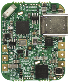
MAXREFDES100 System Board
The platform supports GUI applications on Windows®-based PCs and Android®-based devices for simple data collection and visualization. Both direct USB connection (through a USB type C connector) and Bluetooth® low energy (BLE) radio are supported for configuration and data collections.
A direct-to-flash memory mode is supported for data collection. Flash memory read using a USB connection is also implemented.
The microcontroller of the platform is programmed with firmware that manages the system, controls the registers of all the devices on the platform, and communicates with the PC GUI. For users who want to customize the firmware for the microcontroller, refer to the firmware development guide for details: mbed (referenced as MAX32620HSP).
The following items are included in the reference design box:
- MAXREFDES100 board: the health-sensor board
- MAXREFDES100HDK board: the development board for the MAXREFDES100# sensor board
- Battery holder: for the installation of CR2032-type coin-cell battery if a USB cable is not used
- Two ECG cables: users can solder these two ECG cables to the board for ECG measurements
- USB type-C cable: for the connection between a PC and the MAXREFDES100# board
- Micro-USB cable: for the connection between a PC and the MAXREFDES100HDK# board
The following use cases can be evaluated using this platform:
- Fitness Applications
- Chest-based applications
- Chest straps with HR
- Chest straps with HR & ECG
- Wrist-based applications
- Smart watches with Optical HR
- Ear-based applications
- Headphones with Optical HR
- Clinical applications
- Chest-based applications
- 1 lead-ECG patch for Arrhythmia detection (ECG & HR only)
- Skin temperature measurements
- Finger-based applications
- Optical SpO2 measurement
- Ear-based applications
- Optical HR & SpO2
- Head-based applications
- Optical HR & SpO2
- Arm-based applications
- Arm bands with ECG
As with all Analog Devices reference designs, the bill of materials (BOM), schematics, layout files, Gerber files, firmware, and software are all available online.
System Diagram


The MAX32620 microcontroller lies at the center of the hSensor platform. The following sensors are installed: MAX30003/MAX30004 biopotential analog front-end (AFE), MAX30205 human body temperature sensor, MAX30101 pulse oximeter and heart-rate sensor, LIS2DH 3-axis accelerometer, LSM6DS3 3D accelerometer and 3D gyroscope, and BMP280 absolute barometric pressure sensor.
Power Supplies
The hSensor platform can be powered by a USB connection or by a CR2032-type coin cell battery. When both USB and coin cell are attached the power is drawn from the USB due to MOSFET/Schottky diode at Q4. If a coin cell is attached without USB the coin cell is used to power the hSensor platform.
The hSensor platform uses a MAX14720 PMIC for the majority of the power management. The PMIC has internal programming such that a 3-second button press at SW1 turns the device on. A 20-second press at SW1 turns the PMIC off.
The PMIC has a power-on configuration that provides 1.2V, 1.8V and VSYS voltages. Here VSYS comes from SWOUT, which in turn comes from the battery or USB through the PMIC pin SWIN. After power-up, the microcontroller configures the PMIC for a boost voltage of 3.3V, which appears at the HVOUT pin.
While the PMIC provides the majority of power management there are some additional power supply chips. The temperature sensors are powered by a MAX8880 LDO, which is powered by HVOUT (3.3V) and regulates this down to 2.5V. The PMIC itself is fed by a MAX8881 3.3V LDO when the hSensor is attached to USB.
ESD protection is provided by the MAX3205, which attaches to all of the USB signals except for DP/DM, which have ESD protection provided by the MAX32620.
Mode selection signals
The hSensor platform uses the USB type C connector for debug (programming) and accessory signals. In some circumstances, these signals would contend with a USB host, so there is circuity to isolate these signals as needed.
The isolation is done with MAX4741 low-voltage analog switches. These switches are controlled by a combination of logic gates and MAX9064 single comparators.
The MAX9064 has an internal comparison voltage of 0.2V and two of them are used to monitor the USB pins A5 and B5 (typically designated as CC/VCONN). The USB A5 and B5 pins have 5.1kΩ pulldowns on the HSP board, a USB cable has a 56kΩ pullup on only pin A5 and a debug adapter board has 56kΩ pullups on both pin A5 and B5.
The following table indicates how the hSensor platform self-configures based on the USB A5 and B5 pins.
| USB Pin A5 | USB PIN B5 | Mode | Connection |
| Low | Low | Accessory | VIO and UART enabled by micro |
| Low | High | USB Cable | All Accessory signals isolated |
| High | Low | ||
| High | High | Debug | SWD, RST, VIO, UART enabled |
MAX32620 Microcontroller
The MAX32620 is a 32-bit ARM® Cortex®-M4F (M4 plus floating point unit) microcontroller, suited for emerging medical and fitness applications. The architecture combines high-efficiency, signal-processing functionality with low cost, and ease of use. The device features 4 powerful and flexible power modes. Built-in dynamic clock gating and firmware controlled power gating minimize power consumption for any application. Multiple SPI, UART, and I2C serial interfaces, as well as a 1-Wire® master and USB, allow for interconnection to a wide variety of external sensors. A four-input, 10-bit ADC with selectable reference is provided.
Refer to the MAX32620 data sheet for details and design resources including evaluation kit, developing tools & user guides.
MAX30003/MAX30004 Biopotential AFE
The MAX30003/MAX30004 is a complete, biopotential AFE solution for wearable applications. It offers high performance for clinical and fitness applications, with ultra-low power for long battery life. The MAX30003/MAX30004 is a single biopotential channel providing ECG waveforms and heart-rate detection.
The biopotential channel has ESD protection, EMI filtering, internal lead biasing, DC leads-off detection, ultra-low power leads-on detection during standby mode, and extensive calibration voltages for built-in self-test. Soft power-up sequencing ensures no large transients are injected into the electrodes. The biopotential channel also has high-input impedance, low noise, high CMRR, programmable gain, various low-pass and high-pass filter options, and a high resolution analog-to-digital converter (ADC). The biopotential channel is DC coupled, can handle large electrode voltage offsets, and has a fast recovery mode to quickly recover from overdrive conditions, such as defibrillation and electrosurgery.
The MAX30003/MAX30004 interface is compatible with SPI/QSPI™/Micro-wire/DSP. In the hSensor platform, the MAX30003/MAX30004 communicates with the MAX32620 microcontroller through an SPI bus.
The MAX30003/MAX30004 is available in a 28-pin TQFN and 30-bump wafer-level package (WLP), operating over the 0°C to +70°C commercial temperature range.
For users who want to connect the ECG cables for measurement, remove R6, R21, R44, and R45 on the sensor board. Solder ECG cables on ECGP and ECGN pads on the sensor board.
Refer to the MAX30003/MAX30004 data sheet for details.
MAX30205 Human Body Temperature Sensor
The hSensor board has two MAX30205 installed, one on the top side and one on the bottom side.
The MAX30205 temperature sensor accurately measures temperature and provides an overtemperature alarm/interrupt/shutdown output. This device converts the temperature measurements to digital form using a high-resolution, sigma-delta ADC. The accuracy of the MAX30205 meets the clinical thermometry specification of the ASTM E1112 when soldered on the final PCB. Communication is through an I2C-compatible, 2-wire serial interface.
The I2C serial interface accepts standard write byte, read byte, send byte, and receive byte commands to read the temperature data and configure the behavior of the open-drain overtemperature shutdown output.
The MAX30205 features three address select lines with a total of 32 available addresses. The sensor has a 2.7V to 3.3V supply-voltage range, low-600µA supply current, and a lockup-protected I2C-compatible interface that make it ideal for wearable fitness and medical applications.
In the hSensor platform, the top side MAX30205 (U2) I2C address is 0b1001-001x, the bottom side MAX30205 (U12) I2C address is 0b1001-000x.
This device is available in an 8-pin TDFN package and operates over the 0°C to +50°C temperature range.
Refer to the MAX30205 data sheet for details.
Quick Start Guide for PC Application
Download the latest MAXREFDES100# PC GUI program MAXREFDES100SWxxx.zip and serial driver MAXREFDES100SerialDriverxxxx.zip located at the MAXREFDES100# web page.
Required equipment:
- MAXREFDES100# board
- A PC with a spare USB port
- One USB type A to C cable
Procedure
The MAXREFDES100# board is fully assembled and tested. Use the following steps below to verify proper board operation.
- Unzip the hSensor serial port driver MAXREFDES100SerialPortDriverxxxx.zip to a local folder. MAXREFDES100SerialPortDriverxxxx.zip to a local folder.
- Unzip the PC GUI program MAXREFDES100SWxxx.zip to a local folder and run MAXREFDES100SWxxx.exe to install the program on the PC.
- Run the GUI program and ignore the following pop up window. Click OK to continue
- Click Cancel button on the following pop up window:
- The GUI program should appear as follow:
- Connect the hSensor board to the PC with the USB A to C cable.
- Press and hold the SW1 switch on the hSensor board for 3 seconds and then release. During this time, the PC looks for the device driver for the hSensor if the Analog Devices hSensor serial driver has not been installed on this computer.
- Open the Device Manager window, the hSensor is enumerated as CDC Device as shown in the following window:
- Right click CDC DEVICE and then click Update Driver Software... to finish the driver installation. The driver is located where MAXREFDES100SerialPortDriverxxxx.zip was unzipped.
- After the driver installation is done, the hSensor is enumerated as a serial port and the Device Manager should display as below:
- Go back to the hSensor GUI program, click Device menu, and then click Connect menu item, the GUI program should be connecting to the hSensor hardware. The following window should appear. Check the status bar, verify the hardware is connected.
- In the future sessions, launch the GUI program by clicking the Start menu and selecting the Analog Devices Integrated folder and then selecting Health Sensor Platform software icon. The GUI should automatically connect to the sensor board. If a connection screen pops up, select the right serial port number and click the Connect button as shown below:
Detailed Software Description
The GUI program enables users to quickly configure and evaluate the sensors' features. It also provide intuitive graphs for data collection and visualization.
The File menu lets a user exit the application.
The Device menu lets a user connect and disconnect the hSensor hardware from the GUI program.
The Options menu lets a user show or hide the MAX30003/MAX30004 register names on the GUI, load or save device register settings, and enable or disable Advanced tab.
The Logging menu lets a user log ECG, R-to-R, optical, and accelerometer sensor data in a CSV file format.
The Help menu shows the program information.
Home Tab
The Home tab sheet (Figure 7) displays the block diagram of the hSensor platform hardware, it also provides quick links to navigate to other tab sheets.
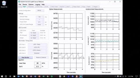
Optical Tab
The Optical tab sheet (Figure 9) is used to configure the MAX30101 optical sensor parameters. It includes the sensor mode configuration, sensor ADC configurations, and LED settings. It also has graphs to show ADC codes and the LIS2DH accelerometer measurements. Click Start Monitor button to plot optical and acceleration measurements. Click Stop Monitor button to stop the measurements. . Click Start Monitor button to plot optical and acceleration measurements. Click Stop Monitor button to stop the measurements.

Figure 9. Optical tab.
Temperature Tab
The Temperature tab sheet (Figure 10) controls the two MAX30205 temperature sensors on the top and bottom sides of the hSensor board.
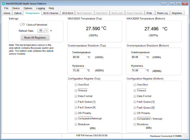
Figure 10. Temperature tab.
ECG Channel Tab
The ECG Channel tab sheet (Figure 11) controls the MAX30003/MAX30004 ECG channel and R-to-R settings.

Figure 11. ECG Channel tab.
ECG MUX Tab
The ECG MUX tab sheet (Figure 12) controls the MAX30003/MAX30004 input multiplexers' settings. A typical setting is shown below:

Figure 12. ECG MUX tab.
Best Practices for Measuring ECG
- When streaming data to the GUI using the USB-C cable, use a laptop running from battery power to eliminate the noise from the power supply and to avoid being patient connected because isolation is not built into the Health Sensor Platform.
- Disconnect other devices from the laptop such as monitors and projectors to reduce interference.
- Move the board and ECG cables away from sources of electrical noise and closer to the body where the electrodes are placed.
- Long unshielded ECG cables are very susceptible to picking up noise, so using short and/or twisted ECG cables and keeping them close to the body where the electrodes are reduces coupled noise.
- Shielded ECG cables that are grounded to the PCB might reduce noise coupling.
- Using no ECG cables and moving the PCB close to the body being measured improves performance.
- Connecting a third electrode between the RL position or similar on the body and the VCM test point on the Health Sensor Platform PCB acts as a body bias and reduces coupled noise.
Plots Tab
The Plots tab sheet (Figure 13) displays MAX30003/MAX30004 ECG measurement values and input MUX status.

Figure 13. Plots tab.
Flash Log Tab
The Flash Log tab sheet (Figure 14) allows users to configure data logging to flash memory. The Read button reads the current configured settings from flash memory and applies it to the UI. The Erase button clears the data-logging settings. The Write button commits the data log settings to flash memory by selecting the desired logging channels and parameters on this tab. This also clears any data values stored on the flash memory. For optical, and MAX30003/MAX30004 settings, use the drop-down options on their respective tabs. The Advanced button shows the raw command parameters from the UI or settings read from flash memory. The Prefix and Suffix fields allow users to execute custom commands. The Save to File button downloads the data from the flash memory to one or more CSV files. The Write button and Save to File button operations may require a long period of time to complete depending upon the amount of data stored on the flash memory.

Figure 14. Flash Log tab.
Registers Tab
The Registers tab sheet (Figure 15) lists all the registers for the MAX30101, MAX30205 (top), MAX30205 (bottom), MAX30003/MAX30004, MAX14720, and the LIS2DH. A user can directly read or write the registers.

Figure 15. Registers tab.
Quick Start Guide for Android Application
The hSensor Android App is a GUI program running on an Android device. The program collects hSensor data and graphically displays it on the device screen. The program communicates with the hSensor hardware through Bluetooth 4.0 Low Energy radio.
Required Equipment:
- MAXREFDES100# board
- Android device running at least version 4.4
- Android device with Bluetooth 4.0 support
- One CR2032 coin cell battery (optional)
- A PC with a spare USB port (optional if battery powered)
- One USB type A to C cable (optional if battery powered)
Procedure
- Insert the CR2032 battery into the battery holder B1.
- If no battery is available, connect the hSensor platform hardware to a PC or Mac though a USB type C connector.
- Press and release SW1 switch on the board. The red LED beside the switch should flash.
- Download the latest MAXREFDES100# Android app MAXREFDES100_Androidxxx.zip located at the MAXREFDES100# web page. Unzip it and install it on the device. The app requires Android 4.4 or later.
- Tap the MAXREFDES100 icon to start the hSensor Android App.
- Tap the Scan button at the bottom of the screen. The scan lists all of the devices currently advertising using Bluetooth 4.0.
- Tap the MAXREFDES100 device in the list to connect to the hSensor platform hardware.
- The following screen shows up.
hSensor Interaction
The hSensor platform sensors are listed when the device is connected. Temperature, accelerometer and pressure are shown. Heart-rate information can be shown from the MAX30003/MAX30004 ECG device.
The hSensor initially does not contain ECG configuration parameters and the default configuration is ECG and R-to-R enabled with internal self-calibration running at 4Hz so it display as a 240bpm heart rate. The ECG can be custom configured by using the GUI on the ECG Channel, ECG Mux, and the Flash Log tabs shown in Figures 11, 12, and 14. The GUI Advanced button under the Flash Log tab shows the raw command parameters from the UI and allows for further custom configuration. In addition to the ECG parameters, the accelerometer needs to be enabled when writing this configuration into the hSensor. The temperature sensors and pressure sensor is always shown when using the Android app and do not require configuration. The Write button within the GUI commits the new configuration into the hSensor. This configuration is used when pressing the Start button on the Android app.
After the GUI is used to provide ECG configuration, the ECG leads must be connected to the hSensor platform and to the body in order to show a correct reading. After connecting the leads, click the Start button on the screen. The platform starts sampling ECG R-to-R information and displays the resulting heart rate on the screen in addition to the temperature, accelerometer, and barometer data.
Disconnecting
The hSensor device may be disconnected by pressing the DISCONNECT button found at the top of the screen.
Firmware Description
The MAXREFDES100# firmware is based on an interrupt-driven design model. After power-up, the microcontroller configures the power management device and sensors to their default settings. The microcontroller then waits for remote procedure calls (RPC) from GUI or Android application.
The following is the simplified firmware flowchart:
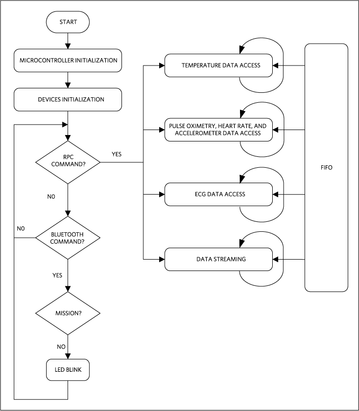
Figure 19. Firmware Flowchart V10.
1-Wire is a registered trademark of Analog Devices Integrated Products, Inc.
Android is a registered trademark of Google Inc.
ARM is a registered trademark and registered service mark and Cortex is a registered trademark of ARM Limited.
The Bluetooth word mark and logos are registered trademarks owned by Bluetooth SIG, Inc. and any use of such marks by Analog Devices is under license.
QSPI is a trademark of Motorola, Inc.
Windows is a registered trademark and registered service mark of Microsoft Corporation.
Documentation & Resources
-
MAXREFDES100 Design Files2/16/2021ZIP35 M
Support & Training
Search our knowledge base for answers to your technical questions. Our dedicated team of Applications Engineers are also available to answer your technical questions.