Abstract
This article describes the various tools available for switch-mode power supply developments. These tools work together to guide a designer from the initial power management architecture of a system all the way to final evaluation in hardware. Each tool serves a specific purpose and offers valuable insights. These capabilities allow an engineer to design superior power supplies within a reduced development time.
Introduction
Almost all electronic circuitry needs a power supply. Thus, most design engineers must devise a power supply solution to power their circuitry. To make this task simpler, an extensive power supply tool chain has been developed over time. Generally, we can distinguish between five different tools: power system designers, power supply calculation tools, digital power supply setting tools, circuit simulation tools, and hardware evaluation tools. All these tools perform separate functions and make the life of a hardware designer much simpler.
Power System Designers
System design tools help with the architecture for a system’s power supplies. Most electronic systems require more than one single power supply. Often five or more different power supplies are needed. The LTpowerPlanner® tool from Analog Devices allows designers to draw a simple block diagram of all the different power conversion steps in a circuit. These can be modified in an easy to use graphical user interface. Each power supply block can be set to an expected power conversion efficiency so that a user will find the total power supply architecture efficiency within a few mouse clicks. Figure 1 shows a screenshot of one of those block diagrams with a calculated total efficiency of 86.3%.

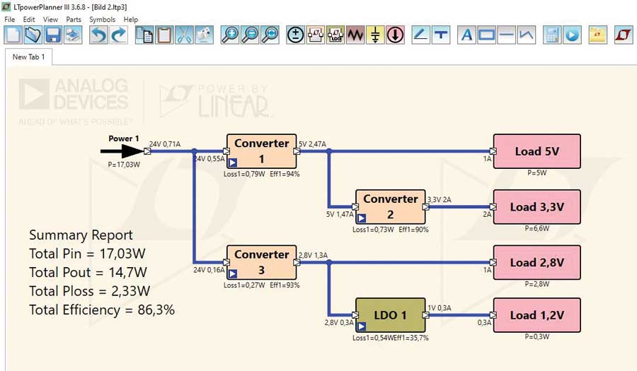
This tool helps to make basic decisions for the power architecture by selecting DC-to-DC converters with an individual efficiency to yield an acceptable total power conversion efficiency. Also, system-level decisions, such as sequencing requirements and capabilities, can be made and recorded.
Power Supply Calculation Tools
After developing a suitable power system design for a specific application using LTpowerPlanner, we focus on a particular DC-to-DC converter to design and optimize that specific circuit. The best supporting tool for this design step is LTpowerCAD®. It can be downloaded for free from the ADI website and it is locally installed on a user’s machine. Network connectivity is only required for updates or for accurate calculation of inductor core losses. Once LTpowerCAD is installed and started, the user can select an existing power converter IC from a parametric search window. Enter the input voltage range and required output voltage and output current as well as other specific requirements such as a power good pin, frequency synchronizability, or digital interfacing. Then a list of suitable components is shown. The user then selects one solution from the list and a design window opens with suggested values for external components. Select real components from a long list of real inductor or capacitor devices from multiple vendors. These are then utilized for a complete calculation of an optimized circuit including circuit efficiency, stability considerations, and additional filtering requirements on the input side or on the output side of the power converter.
When working with the tool, warning messages are given if a component value is chosen with a much lower or higher value than the circuit calculation suggests.
Figure 2 shows the main window for design optimization within LTpowerCAD. Yellow fields display the calculated values by the tool and blue fields allow value entry by a user. Designing the circuit of a switch-mode power supply is simple using this tool.

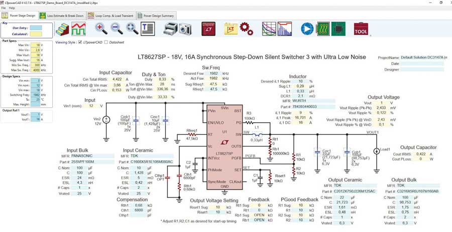
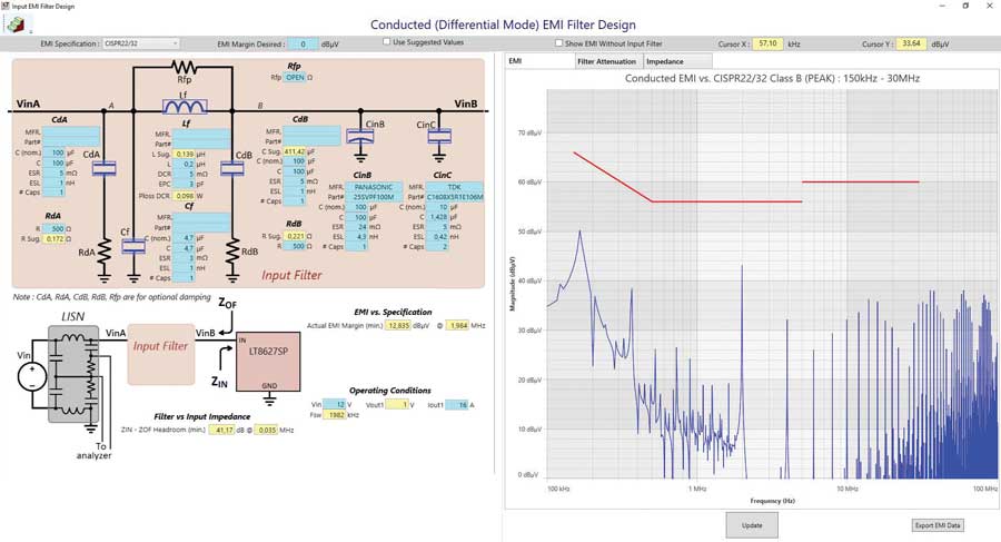
Figure 3 shows a unique feature within LTpowerCAD: the electromagnetic interference (EMI) filter designer tool. It can be accessed on the main circuit screen of LTpowerCAD and opens a special filter designer window. This filter designer is great for discovering if a power supply requires a special input filter to fulfill certain conducted EMI specifications such as CISPR 22/CISPR 32, CISPR 25, or MIL-STD-461G emissions. The filter designer will plot the emissions of the power converter itself, and it will suggest a suitable input side filter to attenuate the conducted emissions to an acceptable level. Besides these main tasks, the filter transfer function (filter attenuation) and the filter impedance are plotted. Filter impedance is very important to ensure the combination of DC-to-DC converter and filter is stable.

Digital Power Supply Setting Tools
Some power supplies are digital. Most certainly, ones and zeroes do not power a load. What we mean by digital power supplies is a digital circuit within a power supply regulator IC to control circuit parameters, read information about the power supply activities (telemetry), and enables the ability to run the complete control loop in the digital domain. While this requires higher effort in digitizing signals quickly and accurately, it offers the capability to digitally adapt the control loop.
When evaluating digital power supplies, we need a software tool to talk to the power supply and make various settings to the state machine-based devices. For this a user can download the free of charge LTpowerPlay® tool. It is a graphical user interface to fully control digital power supplies. Typically, the software talks to the hardware using a USB to I2C (PMBus®) interface. Figure 4 shows the main window of LTpowerPlay where different settings can be selected and information from the power supply is polled and displayed.


The LTpowerPlay digital power supply tool can be run as a standalone system in simulation mode, even when no hardware is attached. This makes it possible to quickly learn about a digital power supply IC without having to spend time reading a long data sheet.
Circuit Simulation Tools
There are many circuit simulation tools available on the market. One of the most popular ones is LTspice®. It is a full SPICE simulator with an intuitive schematic entry tool, a symbol generator, and a waveform viewer. It is free of charge and highly advanced. It was optimized for switch-mode power supply simulations. Compared to some SPICE simulators, switch-mode power supply simulations are fast. New features are constantly added and speed is increased.
A circuit simulation tool is a good addition to a circuit calculation tool such as LTpowerCAD. In a simulation tool, a user has increased flexibility to modify a circuit, add circuit parts such as filters, and combine multiple power supplies into one large system to check how multiple power supplies influence each other.
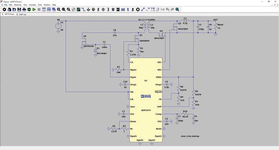
LTspice version 17.1 introduced the frequency response analysis (FRA). It allows a fast and easy way to generate a Bode plot of a power supply regulation loop. LTspice version 24 added a special FRA probe to allow the plotting of partial transfer functions of a regulation loop, while LTspice version 24.1.8 included the ability to plot Nyquist plots and standard Bode plots. Figure 5 shows a power management circuit schematic of an isolated DC-to-DC converter in LTspice.

Besides LTspice, Analog Devices also supports SIMPLIS® with many device models. A node limited version of SIMPLIS can be downloaded for free from the ADI website within the OASIS environment. SIMPLIS is a simulation of piecewise linear systems and is very fast when simulating switch-mode power supplies. The OASIS simulation environment stands for offline analog simulator including SIMPLIS.
Hardware Evaluation Tools
Circuit calculation and simulation is useful and important. However, even with the most modern power management development tool chain, it is still necessary to build a circuit in real hardware and evaluate it. With good preparation of the circuit using the mentioned tools, the hardware evaluation time will be reduced, but still, it is necessary to build and check hardware. To reduce the necessary time in the lab, there is a new power supply evaluation environment called LTpowerAnalyzer. It is a set of hardware that is connected to a PC with the ADALM2000 kit. The ADALM2000 is a pocket scope and signal generator and can control the LTpowerAnalyzer. Figure 6 shows the setup of the LTpowerAnalyzer attached to a design under test (DUT) switchmode power supply board.

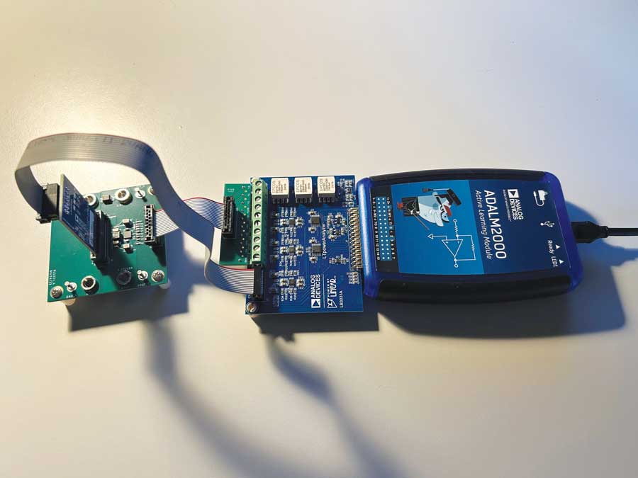
This hardware evaluation tool can plot the Bode plot of a power supply. It can perform life load transient tests for load transients up to 100 A. It can also plot the output impedance of the power supply, which is helpful in discovering if a power supply is compatible with complex (inductive or capacitive) loads.
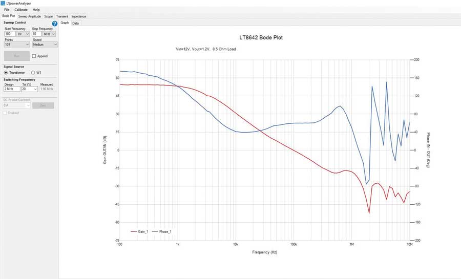
LTpowerAnalyzer can be purchased from the ADI website at a reasonable price. It comes with the LTpowerAnalyzer software, which is quite intuitive. It even allows for interfacing to LTpowerCAD to compare Bode plot calculated results with real hardware measurements. These two plots may be shown in one plot pane window to compare calculation with reality. Figure 7 shows a screenshot of a Bode plot measurement using the LTpowerAnalyzer software.

Conclusion
Designing a power supply is much simpler using the latest power tools for the process. Various steps for optimization are automated and information is presented along the way in a clear and simple manner. Key decisions can be made not only by an experienced power management expert, but also by a circuit designer, who must develop a power supply for the main circuitry. Interestingly, such tools are offered free of charge to users. This makes it easy to get started with the appropriate tool without investment decisions.
