MAX77540
Info : RECOMMENDED FOR NEW DESIGNS
searchIcon
cartIcon

MAX77540

16VIN/6A, Dual-Phase High-Efficiency Buck Converter

Show More showmore-icon

High Efficiency and Power Density Single Step Conversions to Core Voltages from USB-C Rails and Multi cell Batteries

Info : RECOMMENDED FOR NEW DESIGNS tooltip
Part Models 4
1ku List Price Starting From $1.01
Features
  • 4V to 16V Input Voltage Range
  • 0.5V to 5.2V Output Voltage Range
  • Resistor Configurable Default VOUT
  • Two 3A Bucks (1Φ) or One 6A Buck (2Φ)
  • ±0.5% VOUT Accuracy (Default VOUT at 25°C)
  • 94% Peak Efficiency (7.6VIN, 3.3VOUT, 1MHz)
  • Auto SKIP/PWM and Low-Power Mode
  • 98% Max. Duty Cycle Dropout Operation
  • Programmable Soft-Start/Stop and Ramp-Up/Down Slew Rates
  • Pre-Biased Startup and Active Output Discharge
  • Programmable Inductor Peak Current Limits
  • 0.5/1.0/1.6MHz Nominal Switching Frequency
  • Spread-Spectrum Modulation
  • Internal/External Frequency Tracking
  • Dedicated EN, POK, and FPWM Pins
  • Undervoltage lockout (UVLO), Thermal Shutdown, and Short-Circuit Protection
  • High-Speed I2C I/F with 3-Slave Address Options
  • 30-WLP (2.51mm x 2.31mm) and 24-FC2QFN (3mm x 3mm) Packages
  • Less than 55mm2 Total Solution Size
Additional Details
show more Icon

The MAX77540 is a high-efficiency step-down converter with two 3A switching phases. It uses an adaptive COT (constant on-time) current-mode control architecture and the two 3A switching phases can be configured as either one (2Φ, 6A) or two (1Φ, 3A each) outputs. Its wide input voltage range enables a direct conversion for sub-1V outputs from 3-cell Li+ batteries, USB PD, and 12VDC supply rails. The output voltages are preset with resistors and are further adjustable through an I2C-compatible interface. With 94% peak efficiency, low quiescent current, and compact solution size, the MAX77540 is ideal for battery powered, space-constraint equipment.

Programmable switching frequency, frequency tracking, and spread-spectrum allow easier system optimization for noise-sensitive applications. Dedicated EN, POK, and FPWM pins provide options for direct hardware control, while more programmable options, such as soft-start/stop and ramp-up/down slew-rates, are available through I2C. An array of built-in protections insures safe operation under abnormal operating conditions.

Applications

  • 2/3-Cell Li+ and USB-C Power Delivery Systems
  • Audio and Video Equipment
  • Microprocessors, field-programmable gate arrays (FPGAs), digital signal processors (DSPs),andapplication-specific integrated circuits (ASICs)
  • Networking and PCIe®/redundant array of inexpensive disks (RAID) Cards
Part Models 4
1ku List Price Starting From $1.01

close icon

Documentation

Video

Part Model Pin/Package Drawing Documentation CAD Symbols, Footprints, and 3D Models
MAX77540AAFG+
  • HTML
  • HTML
MAX77540AAFG+T
  • HTML
  • HTML
MAX77540AAWV+
  • HTML
  • HTML
MAX77540AAWV+T
  • HTML
  • HTML

Software & Part Ecosystem

Evaluation Kits 1

reference details image

MAX77540EVKIT

Evaluation Kit for the MAX77540 in WLP Package

zoom

MAX77540EVKIT

Evaluation Kit for the MAX77540 in WLP Package

Evaluation Kit for the MAX77540 in WLP Package

Features and Benefits

  • Probe Sockets for High-Accuracy Measurements
  • Test Points for all Features (POK, FPWM, EN, and IRQB)
  • Default Output Voltage Adjustable through SEL
  • Connector for Custom I2C Host

Product Detail

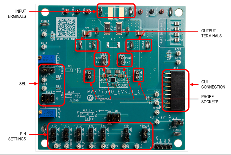
The MAX77540 evaluation kit (EV kit) is a fully assembled and tested printed circuit board (PCB) that demonstrates the MAX77540 dual-phase configurable step-down regulator. The board is equipped with test points and jumpers for testing all pins on the device. Two potentiometers allow the user to adjust the SEL1/SEL2 configuration pins at will. There are also probe sockets on critical nodes (VOUTx, LXx) for precise measurements. The board also comes with some spare inductors (L3-L6) for testing out efficiency/performance tradeoffs. The PCB is designed with Maxim Integrated’s recommended layout of the IC and external components. The IC sets default output voltages by way of R13 and R14 but can be changed with the potentiometers or through I2C communication. Maxim Integrated’s graphical user interface (GUI) can be used by connecting a Windows®-based PC to J11 through a MAXUSB_INTERFACE# device.

Applications

  • 2-cell & 3-cell Li+/Li-ion Systems
  • Devices Powered from USB-C Power Delivery (PD)
  • DSLR, Mirrorless, and HD Video Cameras
  • Embedded Microprocessors, FPGAs, or ASICs
  • Skateboards/Longboards

Tools & Simulations 2

Recently Viewed