

MAX77503
RECOMMENDED FOR NEW DESIGNS14V Input, 1.5A High-Efficiency Buck Converter with 9μA IQ
1.5A Buck Converter with 94% Efficiency for 2-Cell/3-Cell Battery Applications
- Part Models
- 4
- 1ku List Price
- Starting From $0.85
Overview
- 1.5A Single Channel Buck Regulator
- 3V to 14V Input Voltage Range
- 0.8V to 99%VSUP Output Voltage Range
- 0.8V to 5V I2C Programmable in 50mV Steps
- 1.55V to 99%VSUP with External Feedback Resistors
- 1.2V, 1.8V, or 3.3V Factory Preset Options
- High-Efficiency, Low-IQ Extends Battery Life
- 94% Peak Efficiency at 7.4VSUP, 3.3VOUT (2520 Inductor)
- 9µA IQ (12VSUP, 1.8VOUT Internal Feedback Version)
- Selectable Light-Load SKIP and Forced-PWM Modes
- 1MHz or 550kHz Fixed-Frequency Switching
- Hardware or Software Control
- Enable Input and Power-OK Output Pins
- Optional I2C Full Control Interface
- Protection Features
- Cycle-by-Cycle Inductor Peak Current Limit
- Short-Circuit Hiccup Mode, UVLO, and Thermal Shutdown Protections
- 1ms Default Soft-Start
- Small Size
- 1.85mm x 1.4mm (0.7mm max. height) WLP
- 12-Bump, 0.4mm Pitch, 3 x 4 Array
The MAX77503 is a synchronous 1.5A step-down DC-DC converter optimized for portable 2-cell and 3-cell battery- operated and USB-C applications. The converter operates on an input supply between 3V and 14V. Output voltage is adjustable between 0.8V and 5V in 50mV steps through an I2C serial interface or 1.55V to 99% of the supply voltage with external feedback resistors. Factory-programmed default voltages of 1.2V, 1.8V, and 3.3V are offered to reduce component count for common rails. The device features a low-IQ SKIP mode which allows excellent efficiency at light loads.
Dedicated enable and power-OK pins allow simple hardware control. An I2C serial interface is optionally used for full configuration and control for dynamic voltage scaling and system power optimization.
Built-in undervoltage lockout (UVLO), output active discharge, cycle-by-cycle current limit, thermal shutdown, and short-circuit protection ensure safe operation under abnormal operating conditions.
The MAX77503 is available in a 12-bump, 0.4mm pitch wafer-level package (WLP).
 Design Solution: How to Extend the Run-Time of Your DSLR/DSLM Camera
Design ›
Design Solution: How to Extend the Run-Time of Your DSLR/DSLM Camera
Design ›
Applications
- 2-cell/3-cell High Power Density Supplies
- Drones, HD Cameras, and Notebook Computers
- Portable Li+/Li-ion Battery Powered Devices
- Space-Constrained Portable Electronics
Documentation
Data Sheet 1
User Guide 1
Design Note 1
Technical Articles 2
Video 1

ADI has always placed the highest emphasis on delivering products that meet the maximum levels of quality and reliability. We achieve this by incorporating quality and reliability checks in every scope of product and process design, and in the manufacturing process as well. "Zero defects" for shipped products is always our goal. View our quality and reliability program and certifications for more information.
| Part Model | Pin/Package Drawing | Documentation | CAD Symbols, Footprints, and 3D Models |
|---|---|---|---|
| MAX77503AEWC+ | Wafer-Level Package 4x3 Bump, Full Array | ||
| MAX77503AEWC+T | Wafer-Level Package 4x3 Bump, Full Array | ||
| MAX77503BEWC33+ | Wafer-Level Package 4x3 Bump, Full Array | ||
| MAX77503BEWC33+T | Wafer-Level Package 4x3 Bump, Full Array |
This is the most up-to-date revision of the Data Sheet.
Software Resources
Can't find the software or driver you need?
Request a Driver/SoftwareTools & Simulations
ADI Power Studio™ Designer
ADI Power Studio™ Designer is the next-generation tool for IC-level, power supply design, guiding engineers to faster, validated solutions.
Learn MoreSoftware Development 1
SIMPLIS Models 1
Evaluation Kits
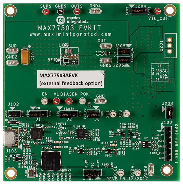
Evaluation Kit for the MAX77503
Resources
Latest Discussions
No discussions on MAX77503 yet. Have something to say?
Start a Discussion on EngineerZone®