LT8640A
Info : RECOMMENDED FOR NEW DESIGNS
searchIcon
cartIcon

LT8640A

42V, 5A/8A Peak Synchronous Step-Down Silent Switcher with 2.5μA Quiescent Current

Show More showmore-icon

Info : RECOMMENDED FOR NEW DESIGNS tooltip
Part Models 8
1ku List Price Starting From $2.68
Features
  • Silent Switcher® Architecture
    • Ultralow EMI Emissions
    • Spread Spectrum Frequency Modulation
  • High Efficiency at High Frequency
    • Up to 96% Efficiency at 1MHz, 12VIN to 5VOUT
    • Up to 95% Efficiency at 2MHz, 12VIN to 5VOUT
  • Wide Input Voltage Range: 3.4V to 42V
  • 5A Maximum Continuous, 8A Peak Transient Output
  • Ultralow Quiescent Current Burst Mode® Operation
    • 2.5μA IQ Regulating 12VIN to 3.3VOUT
    • Output Ripple < 10mVP-P
  • Fast Minimum Switch On-Time: 30ns
  • Low Dropout Under All Conditions: 100mV at 1A
  • Available in Fixed 3.3V Output
  • Forced Continuous Mode
  • Safely Tolerates High Reverse Current
  • Adjustable and Synchronizable: 200kHz to 3MHz
  • Peak Current Mode Operation
  • Output Soft-Start and Tracking
  • Small 18-Lead 3mm × 4mm Side Solderable QFN with Improved Solder Joint Reliability
  • AEC-Q100 Qualified for Automotive Applications
Additional Details
show more Icon

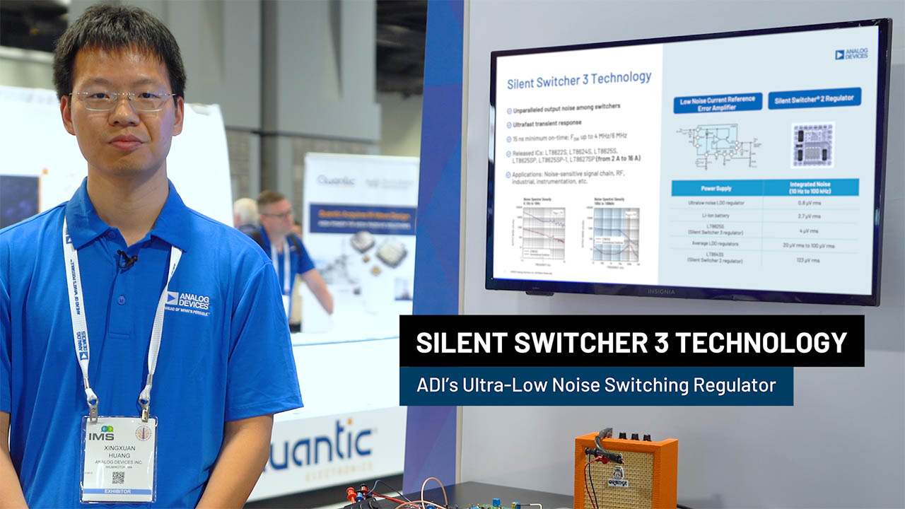
The LT8640A step-down regulator features Silent Switcher architecture designed to minimize EMI emissions while delivering high efficiency at frequencies up to 3MHz. An ultralow 2.5μA quiescent current—with the output in full regulation—enables applications requiring highest efficiency at very small load currents.

The LT8640A allows high VIN to low VOUT conversion at high frequency with a fast minimum top switch on-time of 30ns. The SYNC/MODE pin selects between Burst Mode operation, spread spectrum mode, synchronization to an external clock, and forced continuous mode.

Applications

  • Automotive and Industrial Supplies
  • General Purpose Step-Down
Part Models 8
1ku List Price Starting From $2.68

close icon

Documentation

Video

Part Model Pin/Package Drawing Documentation CAD Symbols, Footprints, and 3D Models
LT8640AJUDCM#PBF
  • HTML
  • HTML
LT8640AJUDCM#TRPBF
  • HTML
  • HTML
LT8640AJUDCM#WPBF
  • HTML
  • HTML
LT8640AJUDCM#WTRPBF
  • HTML
  • HTML
LT8640AJUDCM-3.3#PBF
  • HTML
  • HTML
LT8640AJUDCM-3.3#TRPBF
  • HTML
  • HTML
LT8640AJUDCM-3.3#WPBF
  • HTML
  • HTML
LT8640AJUDCM-3.3#WTRPBF
  • HTML
  • HTML

Software & Part Ecosystem

Evaluation Kits 1

reference details image

DC3099A

LT8640A | 42V, 5A (8A Peak) Synchronous Step-Down Silent Switcher with 2.5μA Quiescent Current

zoom

DC3099A

LT8640A | 42V, 5A (8A Peak) Synchronous Step-Down Silent Switcher with 2.5μA Quiescent Current

LT8640A | 42V, 5A (8A Peak) Synchronous Step-Down Silent Switcher with 2.5μA Quiescent Current

Product Detail

Demonstration circuit 3099A is a 42V, 5A synchronous step-down Silent Switcher® with spread spectrum frequency modulation featuring the LT8640A. The demo board is designed for 5V output from a 5.7V to 42V input. Meanwhile the LT8640A can operate down to 3.4V inputs. The wide input range allows a variety of input sources, such as automotive batteries and industrial supplies. The LT8640A is a compact, ultralow emission, high efficiency, and high speed synchronous monolithic stepdown switching regulator. The integrated power switches and inclusion of all necessary circuitry reduce the components count and solution size. Special Silent Switcher architecture minimizes EMI emissions. Selectable spread spectrum mode can further improve EMI performance. Ultralow 2.5μA quiescent current in Burst Mode® operation achieves high efficiency at very light loads. Fast minimum on-time of 30ns enables high VIN to low VOUT conversion at high frequency.

The LT8640A switching frequency can be programmed either via oscillator resistor or external clock over a 200kHz to 3MHz range. The default frequency of demo circuit 3099A is 2MHz. The LT8640A SYNC/MODE pin on the demo board is grounded (JP1 at BURST position) by default for low ripple Burst Mode operation. Spread spectrum mode and forced continuous mode can be selected respectively by moving JP1 shunt. To synchronize to an external clock, move JP1 to FCM/SYNC and apply the external clock to the SYNC terminal.

The LT8640A data sheet gives a complete description of the part, operation, and application information. The data sheet must be read in conjunction with this demo manual for demo circuit 3099A. The LT8640A is assembled in a 3mm × 4mm plastic QFN package with exposed pad for low thermal resistance. The layout recommendations for low EMI operation and maximum thermal performance are available in the data sheet section Low EMI PCB Layout and Thermal Considerations and Peak Output Current.

Tools & Simulations 1

LTspice® is a powerful, fast and free simulation software, schematic capture and waveform viewer with enhancements and models for improving the simulation of analog circuits.

To launch ready-to-run LTspice demonstration circuits for this part:

Step 1: Download and install LTspice on your computer.

Step 2: Click on the link in the section below to download a demonstration circuit.

Step 3: If LTspice does not automatically open after clicking the link below, you can instead run the simulation by right clicking on the link and selecting “Save Target As.” After saving the file to your computer, start LTspice and open the demonstration circuit by selecting ‘Open’ from the ‘File’ menu.

Recently Viewed