

ADPL13602
RECOMMENDED FOR NEW DESIGNS3.5V to 36V, 2.4A, High-Efficiency, Synchronous Step-Down DC-DC Converter
- Part Models
- 2
- 1ku List Price
- Starting From $0.76
Overview
- Reduces External Components and Total Cost
- No Schottky—Synchronous Operation
- Internal Compensation Components
- All-Ceramic Capacitors, Compact Layout
- Reduces the Number of DC-DC Regulators to Stock
- Wide 3.5V to 36V Input
- Adjustable Output Voltage Range from 1V up to 90% of VIN
- Delivers Up to 2.4A Over the Temperature Range
- 400kHz to 1.5MHz Adjustable Frequency
- Reduces Power Dissipation
- Peak Efficiency of 95%
- Wide 2.4V to 12V Bootstrap Bias Input (EXTVCC) for Improved Efficiency
- Operates Reliably in Adverse Industrial Environments
- Hiccup-Mode Overload Protection
- Adjustable and Monotonic Startup with Prebiased Output Voltage
- Built-in Output-Voltage Monitoring with RESET
- Programmable EN/UVLO Threshold
- Wide Industrial -40°C to +125°C
- Ambient Operating Temperature Range or -40°C to +150°C Junction Temperature Range
The ADPL13602 is a high-efficiency, synchronous stepdown DC-DC converter with integrated MOSFETs operating over an input-voltage range of 3.5V to 36V. It can deliver up to 2.4A current. Output voltage is programmable from 1V up to 90% of VIN. Built-in compensation across the output-voltage range eliminates the need for external compensation components.
The ADPL13602 features a peak-current-mode control architecture. The ADPL13602 can be operated in forced pulse-width modulation (PWM) or discontinuousconduction mode (DCM) to enable high efficiency under full-load and light-load conditions. The ADPL13602 offers a low minimum on-time that allows high switching frequencies and a smaller solution size.
The feedback-voltage regulation accuracy over -40°C to +125°C is ±1.5%. The device is available in a 16-pin (3mm x 3mm) TQFN-EP package. Simulation models are available.
APPLICATIONS
- Industrial Control Power Supplies
- Distributed Supply Regulation
- Wall Transformer Regulation
- High-Voltage, Single-Board Systems
Documentation
Data Sheet 1
Brochure 1
ADI has always placed the highest emphasis on delivering products that meet the maximum levels of quality and reliability. We achieve this by incorporating quality and reliability checks in every scope of product and process design, and in the manufacturing process as well. "Zero defects" for shipped products is always our goal. View our quality and reliability program and certifications for more information.
| Part Model | Pin/Package Drawing | Documentation | CAD Symbols, Footprints, and 3D Models |
|---|---|---|---|
| ADPL13602BATE+ | LFCSP | ||
| ADPL13602BATE+T | LFCSP |
This is the most up-to-date revision of the Data Sheet.
Software Resources
Can't find the software or driver you need?
Request a Driver/SoftwareHardware Ecosystem
| Parts | Product Life Cycle | Description |
|---|---|---|
| MAX17662 | RECOMMENDED FOR NEW DESIGNS | 3.5V to 36V, 2A, High-Efficiency, Synchronous Step-Down DC-DC Converter |
Tools & Simulations
ADI Power Studio™ Designer
ADI Power Studio™ Designer is the next-generation tool for IC-level, power supply design, guiding engineers to faster, validated solutions.
Learn MoreSIMPLIS Models 1
Evaluation Kits
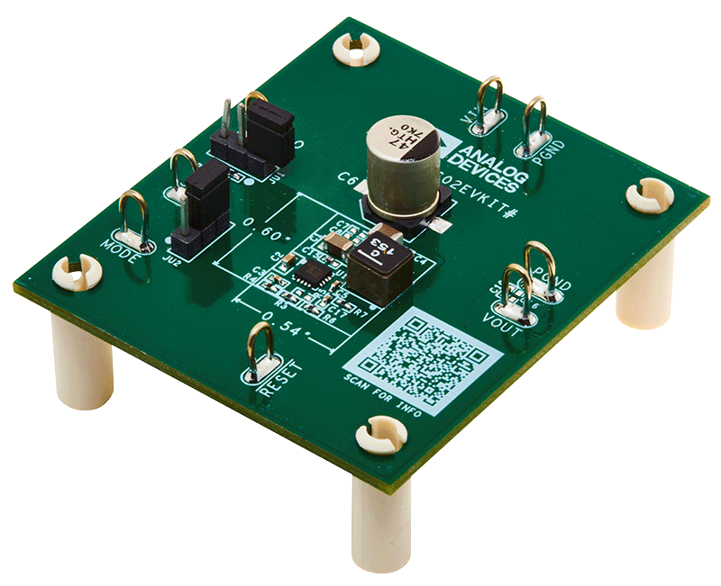
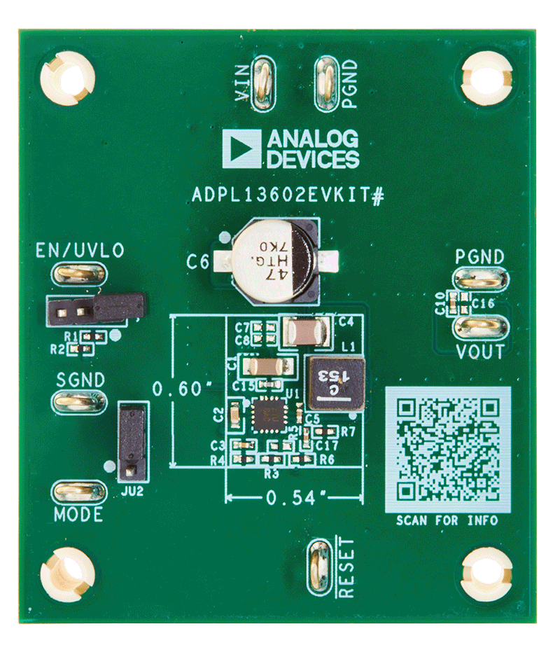
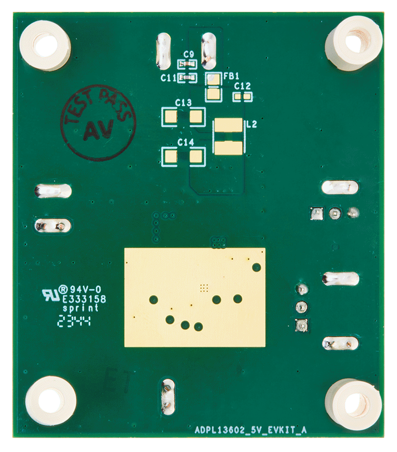
Evaluates: ADPL13602 in 5V Output-Voltage Application
Resources


ADI Balanced Solutions Essentials Kit for the ADPL76030/ADPL26001 / ADPL13602 / ADPL54203 / ADPL20502 / ADPL62933 / ADPL62935 / ADPL63164
Latest Discussions
No discussions on ADPL13602 yet. Have something to say?
Start a Discussion on EngineerZone®