MAX77857

RECOMMENDED FOR NEW DESIGNS

2.5V to 16V Input, 7A Switching Current High-Efficiency Buck-Boost Converter

Enable 20W USB PD Sourcing with 1/3 Solution Size

Viewing:

Overview

  • Wide Input Voltage Range: 2.5V to 16V
  • Default Output Voltage
    • 5V with Internal Feedback Resistors
    • 3V to 15V with External Feedback Resistors
  • I2C-Programmable Output Voltage after Startup
    • 4.5V to 15V with Internal Feedback Resistors
    • 3.0V to 15V with External Feedback Resistors, See Table 1
  • Maximum Output Current
    • Buck Mode: Up to 6A
    • Boost Mode: Up to 4A (Boost Ratio ≤ 1.3)
  • 7A Typical Switching Current
  • RSEL Configuration
    • I2C Interface Slave Address
    • Switching Current Limit Threshold
    • Internal/External Feedback Resistors
  • I2C Programming
    • Output Voltage (DVS)
    • Slew Rate of Output Voltage Change
    • Switching Current Limit Threshold
    • Switching Frequency
    • Forced PWM Mode Operation (FPWM)
    • Power-OK (POK) Status and Fault Interrupt Masks
  • Soft-Start
  • Output Active Discharge
  • Open-Drain Power-OK (POK) Monitor and Fault Condition Interrupt (MAX77857B/C Only)
  • Protection Features
    • Undervoltage Lockout (UVLO)
    • Overcurrent Protection (OCP)
    • Overvoltage Protection (OVP)
    • Thermal Shutdown (THS)
  • High Density Interconnect (HDI) PCB not Required (See the PCB Layout Guideline section)
  • Available in 2.83mm x 2.03mm 35 WLP or 31 WLP or 3.5mm x 3.5mm 16 FC2QFN
MAX77857
2.5V to 16V Input, 7A Switching Current High-Efficiency Buck-Boost Converter
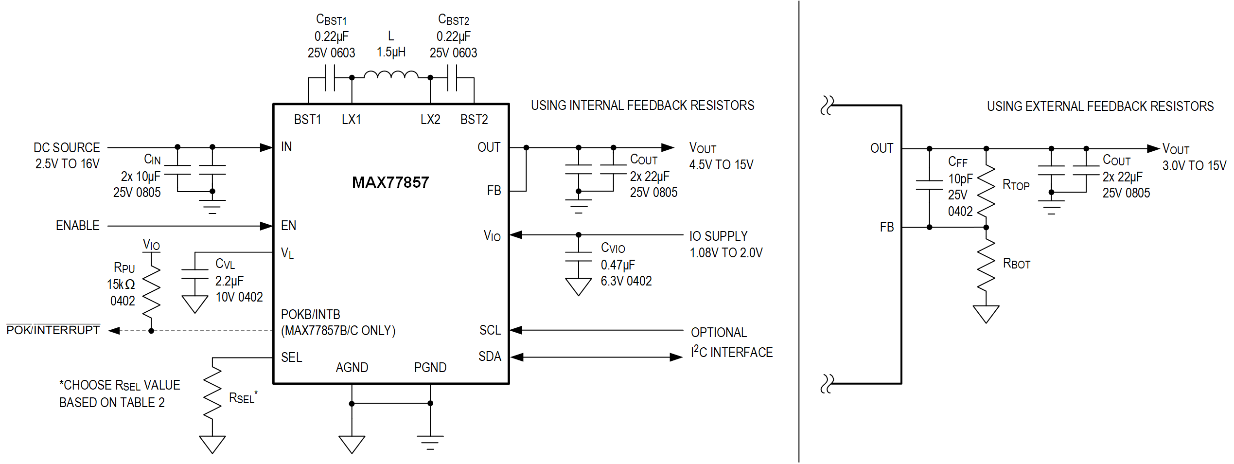
MAX77857 Simplified Application Circuit MAX77857 Pin Configuration
Add to myAnalog

Add product to the Products section of myAnalog (to receive notifications), to an existing project or to a new project.

Create New Project
Ask a Question

Documentation

Learn More
Add to myAnalog

Add media to the Resources section of myAnalog, to an existing project or to a new project.

Create New Project

Software Resources

Can't find the software or driver you need?

Request a Driver/Software

Tools & Simulations

ADI Power Studio™ Designer

ADI Power Studio™ Designer is the next-generation tool for IC-level, power supply design, guiding engineers to faster, validated solutions.

Open Tool

Software Development 1

SIMPLIS Models 1


Evaluation Kits

MAX77857WEVKIT

Evaluation Kit for the MAX77857

Features and Benefits

  • Proven PCB Reference Design and Layout Benefit
  • Fully Assembled and Tested
  • Sense Points for High-Accuracy Measurements
  • Accessible Test Point Pins for EN, POKB/INTB, VIO, and I2C Serial Interface SCL, SDA
  • MAXUSB_INTERFACE# Allows Easy Communication with a Windows PC
  • GUI Software that Drives I2C Serial Interface for Optional Software Control
  • Startup Output Voltage Adjustable Through External Feedback Resistors
  • Output Voltage Dynamically Adjustable Through I2C Serial Interface
  • I2C Slave Address, Switching Current Limit, and Feedback Configuration Adjustable Using RSEL (R9)

Product Details

The MAX77857 evaluation kit (EV kit) is a fully assembled and tested printed circuit board (PCB) that demonstrates the MAX77857, a high-efficiency, high-performance buck-boost regulator with a switching current of 7A. The IC is capable of 2.5V to 16V input and dynamically adjustable output between 4.5V to 15V when using internal feedback resistors, or between 3V to 15V when using external feedback resistors. The EV kit is factory-configured as internal feedback with default startup output voltage at 5V. Other startup voltages can be achieved with external feedback resistors. The output voltage can be adjusted dynamically through the I2C serial interface.

I/O pins are available to support the I2C serial interface, Enable function, and interrupt/Power-OK indicator. The I2C slave address, switching current limit, and feedback configuration can be adjusted by changing the RSEL resistor value (R9). MAXUSB_INTERFACE# allows the use of Windows®-based software with a friendly graphical user interface (GUI) as well as a detailed register-based interface to exercise all features of the IC. The EV kit is compatible with any version of the MAX77857 WLP IC (MAX77857BEWB+T is the default installed on the EV kit).

Applications

  • USB Power Delivery (USB-PD) OTG
  • Qualcomm® Quick ChargeTM
  • USB VBUS Supply and DRP (Dual Role Power) Ports
  • DSLR, DSLR Lens
  • Display Power
  • Up to 3-Cell Li-Ion Battery Applications
  • Notebook Computer, Tablet PC

eval board
MAX77857QEVKIT

MAX77857Q Evaluation Kit

Features and Benefits

  • Proven PCB Reference Design and Layout Benefit
  • Fully Assembled and Tested
  • Sense Points for High-Accuracy Measurements
  • Accessible Test Point Pins for EN, POKB/INTB, VIO, and I2C Serial Interface SCL, SDA
  • MAXUSB_INTERFACE# Allows Easy Communication with a Windows PC
  • GUI Software that Drives I2C Serial Interface for Optional Software Control
  • Startup Output Voltage Adjustable Through External Feedback Resistors
  • Output Voltage Dynamically Adjustable Through I2C Serial Interface
  • I2C Slave Address, Switching Current Limit, and Feedback Configuration Adjustable Using RSEL (R9)

Product Details

The MAX77857Q evaluation kit (EV kit) is a fully assembled and tested printed circuit board (PCB) that demonstrates the MAX77857 in a FC2QFN package, a high-efficiency, high-performance buck-boost regulator with a switching current of 7A. The IC is capable of 2.5V to 16V input and dynamically adjustable output between 4.5V to 15V when using internal feedback resistors, or between 3V to 15V when using external feedback resistors. The EV kit is factory-configured as internal feedback with default startup output voltage at 5V. Other startup voltages can be achieved with external feedback resistors. The output voltage can be adjusted dynamically through the I2C serial interface.

I/O pins are available to support the I2C serial interface, Enable function, and interrupt/Power-OK indicator. The I2C slave address, switching current limit, and feedback configuration can be adjusted by changing the RSEL resistor value (R9). MAXUSB_INTERFACE# allows the use of Windows®-based software with a friendly graphical user interface (GUI) as well as a detailed register-based interface to exercise all features of the IC. The EV kit is compatible with any version of the MAX77857 FC2QFN IC (MAX77857BEFE+T is the default installed on the EV kit).

eval board
MAX77857WGEVKIT

Evaluation Kit for MAX77857 (WLP)

Features and Benefits

  • Proven PCB Reference Design and Layout Benefit
  • Fully Assembled and Tested
  • Sense Points for High-Accuracy Measurements
  • Accessible Test Point Pins for EN, POKB/INTB, VIO, and I2C Serial Interface SCL, SDA
  • Web-Based GUI that Drives I2C Serial Interface for Optional Software Control
  • Startup Output Voltage Adjustable Through External Feedback Resistors
  • Output Voltage Dynamically Adjustable Through I2C Serial Interface
  • I2C Slave Address, Switching Current Limit, and Feedback Configuration Adjustable Using RSEL (R9)

Product Details

The MAX77857 evaluation kit (EV kit) is a fully assembled and tested printed circuit board (PCB) that demonstrates the MAX77857, a high-efficiency, high-performance buck-boost regulator with a switching current of 7A. The IC is capable of 2.5V to 16V input and dynamically adjustable output between 4.5V to 15V when using internal feedback resistors, or between 3V to 15V when using external feedback resistors. The EV kit is factory-configured as internal feedback with a default startup output voltage at 5V. Other startup voltages can be achieved with external feedback resistors. The output voltage can be adjusted dynamically through the I2C serial interface.

I/O pins are available to support the I2C serial interface, enable function, and interrupt/Power-OK indicator. The I2C slave address, switching current limit, and feedback configuration can be adjusted by changing the RSEL resistor value (R9). An onboard MAX32625PICO allows the use of a web-based friendly graphical-user interface (GUI) as well as a detailed register-based interface to exercise all features of the IC. The EV kit is compatible with any version of the MAX77857 WLP IC (MAX77857BEWB+T is the default installed on the EV kit).

eval board
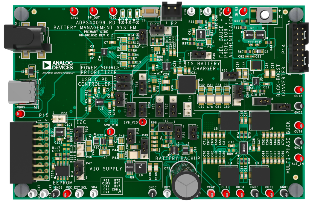
ADPS40099-RD

Handheld Device Battery Power Solution

Features and Benefits

  • Fully integrated single-board solution for portable power and battery management
  • USB-C Power Delivery (PD) input for flexible and modern power sourcing
  • Single-cell (1S) Li-ion battery charger with optimized charge management
  • Advanced fuel gauging, protection, and authentication for battery safety and reliability
  • Multiple configurable output rails (up to 5) supporting diverse system loads
  • Buck-boost and multi-phase buck regulation for efficient power conversion
  • Supercapacitor-based backup power to maintain operation during power loss or battery swap
  • Integrated power path management for seamless source switching
  • Logic-level translation support for multi-voltage system compatibility
  • Compact and scalable design suitable for space-constrained portable devices
  • With MAXUSB_INTERFACE# for easy communication with a Windows PC

Product Details

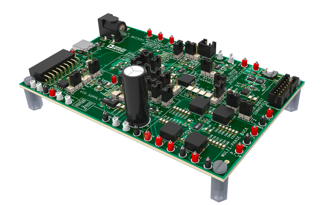
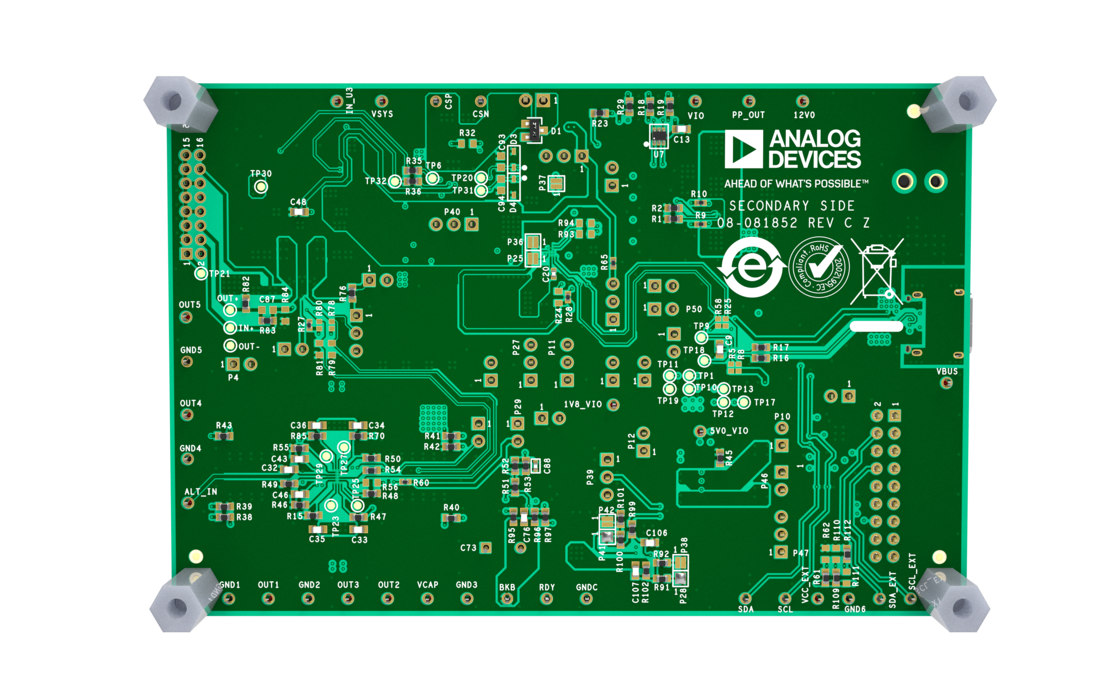
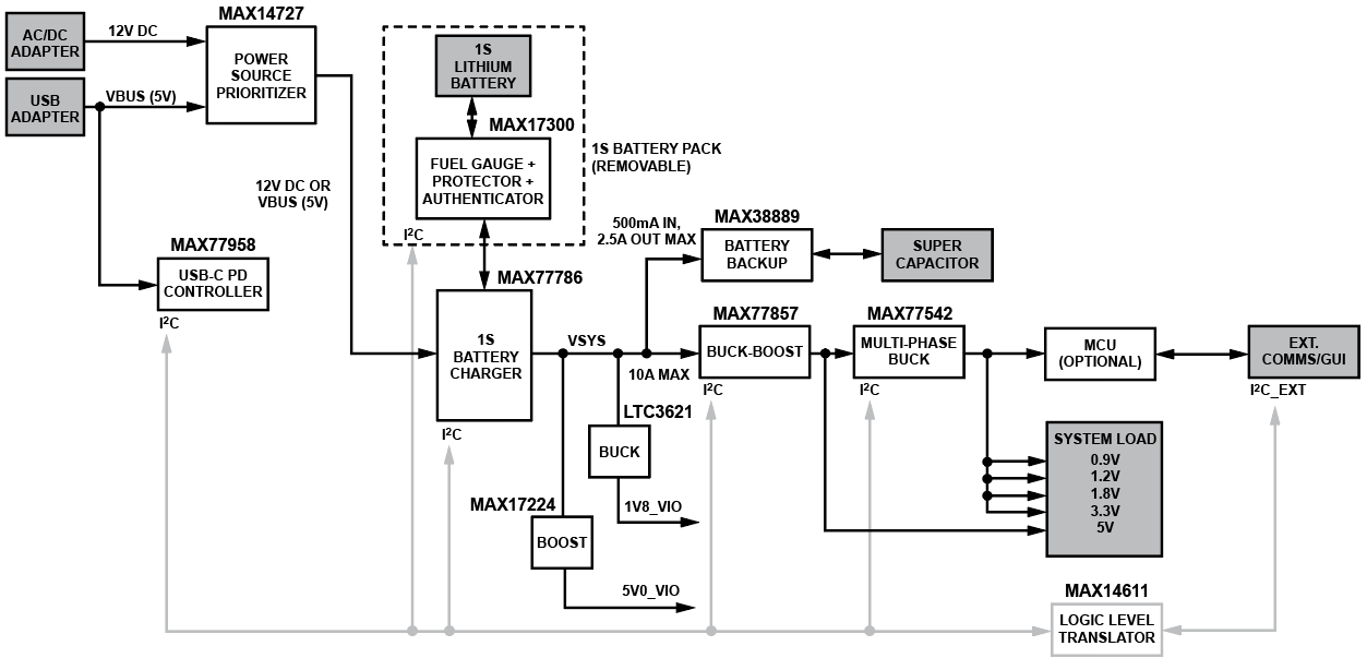
The ADPS40099-RD is a fully integrated battery management system reference design suitable for portable applications. It consolidates a complete power solution for handheld and portable devices, utilizing the latest components from ADI’s power portfolio.

The solution features the MAX77958 USB-C power delivery controller for flexible input options, paired with the MAX77786 1S battery charger to manage charging from a single-cell lithium-ion battery. The MAX17300 provides advanced fuel gauging, battery protection, and authentication capabilities, ensuring safe and reliable operation.

To support diverse power requirements, the design includes the MAX77857 buck-boost regulator and the MAX77542 multi-phase buck converter, enabling up to five individually configurable outputs. The design also integrates the MAX14727 for power path control. For backup power, the MAX38889 utilizes supercapacitor technology to maintain system operation during power interruptions and battery replacements. Additionally, the MAX14611 logic-level translator ensures seamless communication between components operating at different voltage levels.

This compact and cohesive single-board implementation offers a clear advantage in delivering a robust, space-efficient, and scalable battery management solution, ideal for modern portable electronic systems.

MAX77857WEVKIT
Evaluation Kit for the MAX77857
MAX77857QEVKIT
MAX77857Q Evaluation Kit
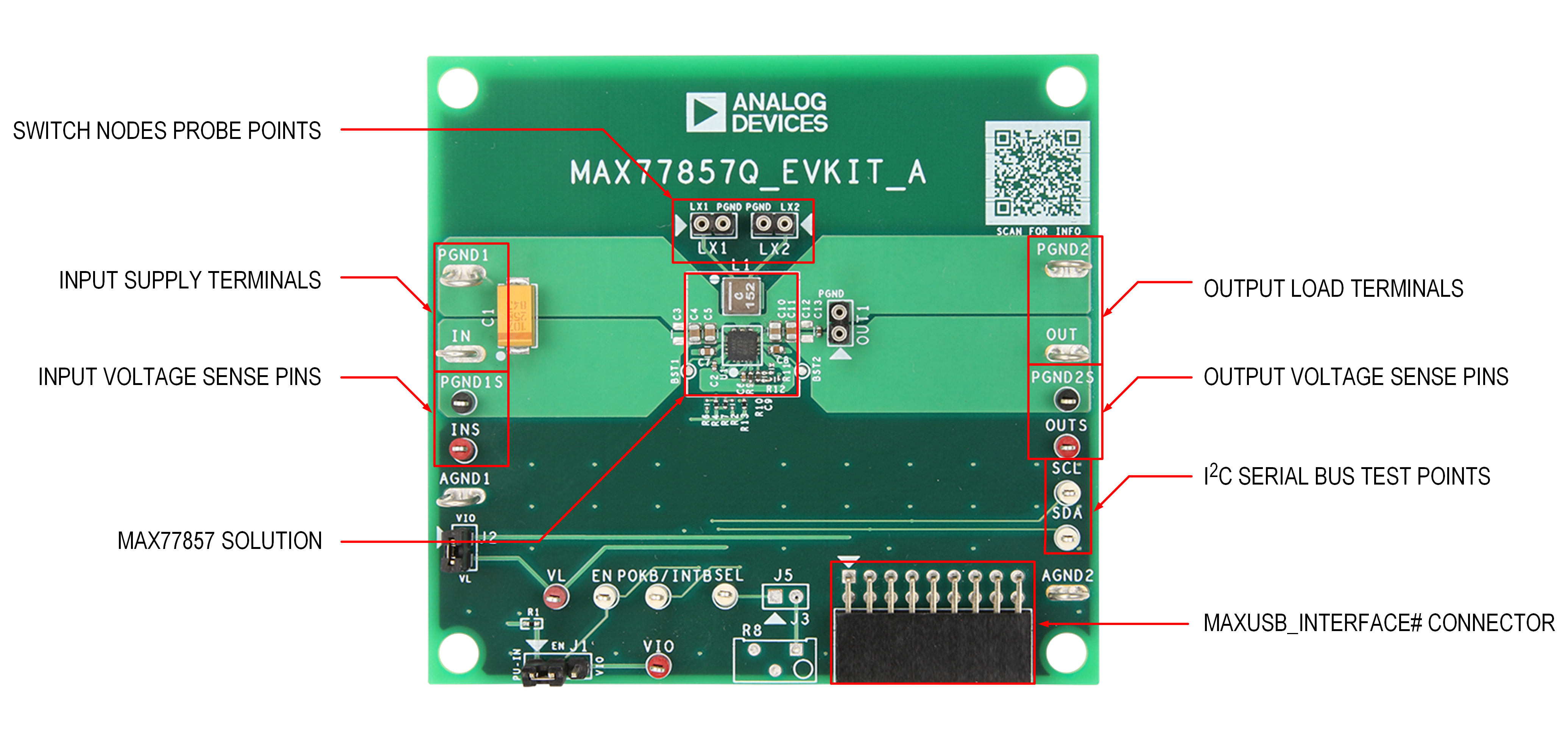
MAX77857Q Evaluation Board MAX77857 Typical Application Circuit
MAX77857WGEVKIT
Evaluation Kit for MAX77857 (WLP)
MAX77857WGEVKIT Board Photo Angle MAX77857WGEVKIT Board Photo Top MAX77857WGEVKIT Board Photo Bottom
ADPS40099-RD
Handheld Device Battery Power Solution
ADPS40099-RD Top Angle Evaluation Board ADPS40099-RD Top Evaluation Board ADPS40099-RD Bottom Evaluation Board ADPS40099-RD Simplified Block Diagram

Latest Discussions

Recently Viewed