MAX20433

PRE-RELEASE

Four-Output, Low-Noise PMIC for Safety Applications

Viewing:

Overview

  • Multiple Functions for Small Size
    • 3A Synchronous High-Voltage Buck Converter
      • Input Voltage Range 3.5V to 40V
      • Output Voltage of 3.3V
    • 5V Synchronous 0.5A Boost Converter
    • Dual 3.2A Low-Noise Buck Converter
      • 0.5V to 3.6875V in 12.5mV Steps
    • Flexible Power Sequencer
    • Programmable Challenge/Response or Windowed Watchdog
    • I2C Fast-Mode Plus Compatible Interface with Packet Error-Checking Option (PEC)
    • 2.1MHz Internal Operation with Spread Spectrum
    • RESET Output
    • Current-Mode, Forced-PWM Operation
  • High-Precision for ASIL Applications
    • ±1.5% Output Voltage Accuracy
    • ±1% OV/UV Monitoring
    • MAXQ Power Architecture
  • Diagnostics and Redundant Circuits
    • ASIL C Compliant
    • Redundant Reference
    • BIST Diagnostics
    • Fail-Safe on Open Pins
    • Shorted Pin Detection on RESET
  • Mount ID Location Detection
  • Robust for the Automotive Environment
  • Overtemperature and Short-Circuit Protection
  • 5mm x 5mm, Side-Wettable TQFN Package
  • -40°C to +125°C Automotive Temperature

The MAX20433 is a high-efficiency, four-output DC-DC converter with a windowed watchdog. The OUT1 is a synchronous step-down converter that converts vehicle battery voltage to 3.3V at up to 3A. The OUT3 boosts the OUT1 to 5V at up to 0.5A, while the OUT2/4 lownoise, low-voltage, synchronous step-down converters operate from OUT1 and provide a 0.5V to 3.6875V output voltage range at up to 3.2A. The low-noise performance eliminates the need for external LDOs and allows the use of a ferrite bead (LC) filter instead. All outputs achieve ±1.5% output error.

The device features a 2.1MHz fixed-frequency PWM mode for all DC-DC outputs for better noise immunity and load-transient response. The 2.1MHz frequency operation allows for the use of all ceramic capacitors and minimizes the external components. The programmable spread-spectrum frequency modulation minimizes the radiated electromagnetic emissions. Integrated low-RDSON switches improve efficiency at heavy loads and make the layout much simpler with respect to discrete solutions.

The MAX20433 features the MAXQTM power architecture, which provides precision transient performance and phase margin. This allows to obtain the maximum power, performance, and precision while minimizing system cost for any specific application.

The devices are offered with factory-preset output voltages. Other features include soft-start, overcurrent, and overtemperature protection.

Applications

  • Advanced Driver-Assistance Systems (ADAS)

Complete documentation is available upon completion of a Non-Disclosure Agreement (NDA). To request an NDA, click here.

MAX20433
Four-Output, Low-Noise PMIC for Safety Applications
MAX20433 Simplified Block Diagram MAX20433 Chip
Add to myAnalog

Add product to the Products section of myAnalog (to receive notifications), to an existing project or to a new project.

Create New Project
Ask a Question

Documentation

Learn More
Add to myAnalog

Add media to the Resources section of myAnalog, to an existing project or to a new project.

Create New Project

Software Resources

Can't find the software or driver you need?

Request a Driver/Software

Evaluation Kits

eval board
MAX20433EVKIT

Evaluation Kit for MAX20433

Features and Benefits

  • Integrated IC Minimizes Board Area and Layout
  • Input Voltage Range from 3.5V to 36V
  • User-Programmable Settings through I2C
  • Challenge/Response or Simple Windowed Watchdog
  • 2.1MHz Fixed-Frequency Switching with Spread-Spectrum Option
  • Status Monitoring through RESET Pin and I2C StatusRegisters
  • Fully Assembled and Tested
  • Proven PCB Layout with Automotive-Grade Components Tested

Product Details

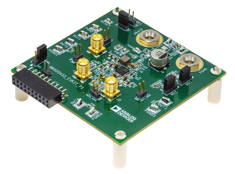
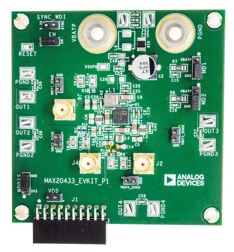
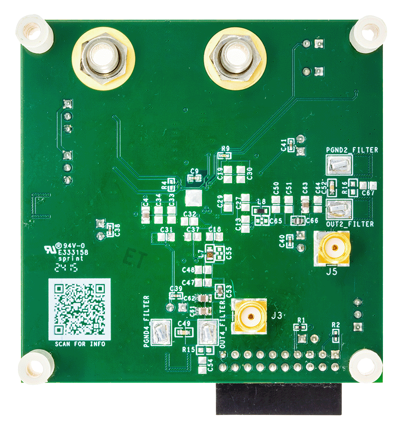
The MAX20433 evaluation kit (EV kit) is a fully assembled and tested application circuit for the MAX20433 high-efficiency, four-output power management IC (PMIC). This EV kit can test all outputs to full load within the normal operation input range of 3.5V to 36V. The IC features two modes of watchdog operation—challenge/response and simple windowed mode—which can also be disabled for simplified evaluation.

To configure the MAX20433 and monitor errors, I2C communication must be used. Using a PC-to-I2C interface such as the MINIQUSB or MAX32625PICO and software such as Simple I2C for reading and writing to I2C registers simplifies testing. Windows®-based graphical-user interface (GUI) software is available for use with the EV kit and can be downloaded from the Analog Devices website at www.analog.com/MAX20433 (under the Design & Development tab). Windows 7 or newer is required to use the EV kit software.

Complete documentation is available upon completion of a Non-Disclosure Agreement (NDA). To request an NDA, click here.

MAX20433EVKIT
Evaluation Kit for MAX20433
MAX20433EVKIT Board Photo Angle View MAX20433EVKIT Board Photo Top View MAX20433EVKIT Board Photo Bottom View

Latest Discussions

No discussions on MAX20433 yet. Have something to say?

Start a Discussion on EngineerZone®

Recently Viewed