MAX20415

RECOMMENDED FOR NEW DESIGNS

2.2MHz Dual-Output, Low-Voltage Step-Down Converters

Viewing:

Overview

  • Multiple Functions for Small Size
    • Dual Synchronous Buck Converters up to 3A
      • Fixed Output Voltage from 0.8V to 3.8V
      • Resistor-Adjustable Output Voltage
    • 3.0V to 5.5V Operating Supply Voltage
    • 2.2MHz Operation
    • Individual EN_ Inputs and RESET_ Outputs I
    • Input Supply Monitoring PV_OV Output
  • High Precision
    • ±1.5% Output-Voltage Accuracy
    • ±1.5% Over/Undervoltage Monitoring Accuracy
    • Good Load-Transient Performance
  • Diagnostics and Redundant Circuits
    • ASIL-C Compliant
    • Redundant Reference
    • Fail Safe on Open Pins
    • Shorted-Pin Detection on RESET1/RESET2
    • Input Overvoltage Detection
  • Robust for the Automotive Environment
    • Current-Mode, Forced-PWM, and Skip Operation
    • Overtemperature and Short-Circuit Protection
    • 4mm x 4mm, 24-Pin TQFN Package
    • -40°C to +125°C Automotive Temperature Range

The MAX20415 is a high-efficiency, dual-output, low-voltage DC-DC converter. The synchronous step-down converters operate from a 3.0V to 5.5V input voltage range and provide a 0.8V to 3.8V output voltage range at up to 3A. The buck converters achieve ±1.5% output error over load, line, and temperature range.

The IC features a 2.2MHz fixed-frequency pulse-width modulation (PWM) mode for better noise immunity and load-transient response, and a pulse-frequency modulation mode (skip) for increased efficiency during light-load operation. The 2.2MHz frequency operation allows for use of all-ceramic capacitors, minimizing the total solution footprint. Programmable spread-spectrum frequency modulation minimizes radiated electromagnetic emissions. Integrated low RDS(ON) switches improve efficiency at heavy loads and make the layout a much simpler task with respect to discrete solutions.

The IC is offered with factory-preset or resistor-adjustable output voltages. Other features include soft-start, over-current protection, pin diagnostics, and overtemperature protections. The MAX20415 is available in a lead(Pb)-free, 24-pin TQFN package (see the Ordering Information/Selector Guide for available options).

APPLICATIONS

  • Automotive ADAS Applications
  • Short-Range Radar
  • MAX20415
    2.2MHz Dual-Output, Low-Voltage Step-Down Converters
    MAX20415 Typical Operating Circuit
    Add to myAnalog

    Add product to the Products section of myAnalog (to receive notifications), to an existing project or to a new project.

    Create New Project
    Ask a Question

    Documentation

    Data Sheet 1

    Request an NDA

    Complete documentation is available upon completion of a Non-Disclosure Agreement (NDA). To request an NDA, click here.

    Learn More
    Add to myAnalog

    Add media to the Resources section of myAnalog, to an existing project or to a new project.

    Create New Project

    Software Resources

    Can't find the software or driver you need?

    Request a Driver/Software

    Evaluation Kits

    eval board
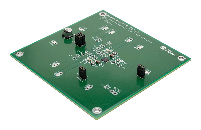
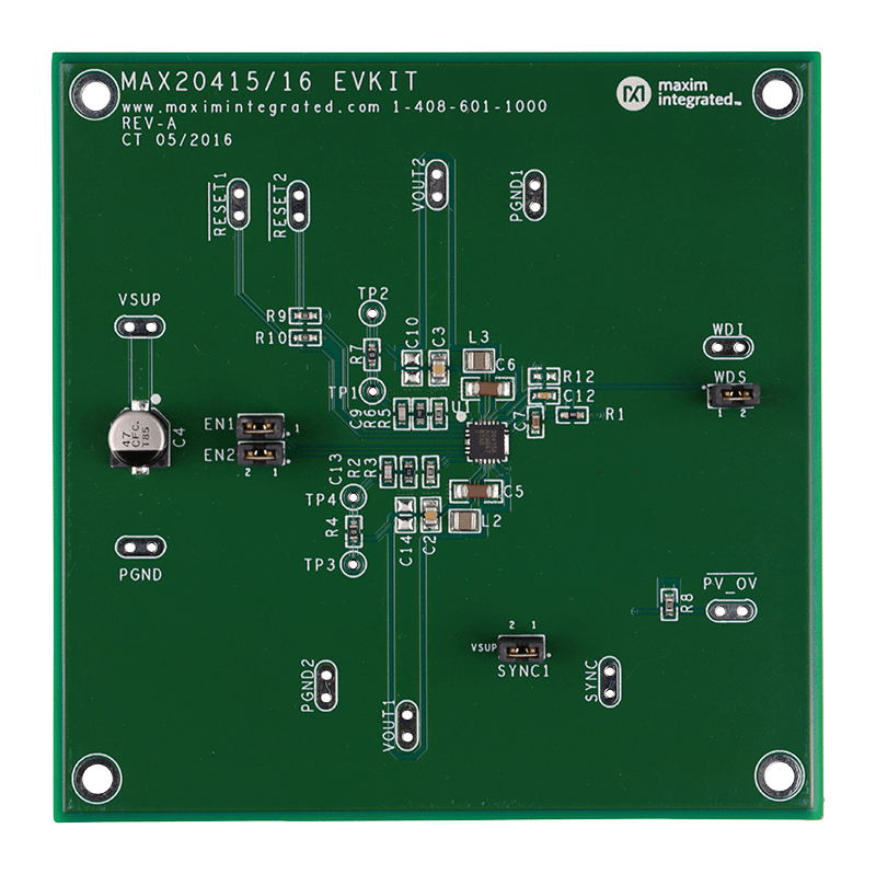
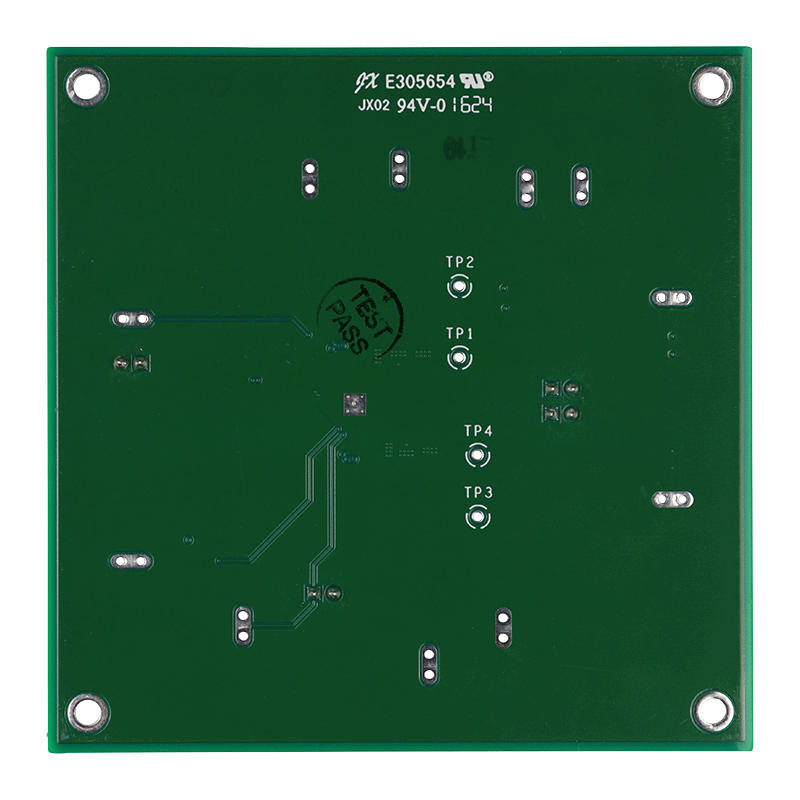
    MAX20415EVKIT

    Evaluation Kit for MAX20415

    Features and Benefits

    • 3.0V to 5.5V Operating Supply Voltage
    • 1.25V at 3A Synchronous Buck Converter (OUT1)
    • 1.8V at 3A Synchronous Buck Converter (OUT2)
    • Programmable Windowed Watchdog
    • Sync-Mode Select Input for Forced-PWM (FPWM), Skip-Mode Selection, or External Frequency Synchronization
    • Individual RESET_ Outputs
    • PV_OV Input Power-Good Indicator
    • Minimized External Components
    • Proven PCB Layout
    • Fully Assembled and Tested

    Product Details

    The MAX20415 evaluation kit (EV kit) is a fully assembled and tested PCB that demonstrates the MAX20415 highefficiency, low-voltage DC-DC converter. The synchronous step-down converters operate from a 3.0V to 5.5V input voltage range and provide a 0.8V to 3.8V output voltage range at up to 3A. The 2.2MHz switching-frequency operation allows for the use of all-ceramic capacitors and minimizes external components.

    The EV kit features two on/off jumper controls and two reset outputs to indicate output status for each converter. It also provides a sync input to select the operating mode (PWM, skip, or external synchronization), and a PV_OV output as an input power-good indicator.

    MAX20415EVKIT
    Evaluation Kit for MAX20415
    MAX20415EVKIT Angle MAX20415EVKIT Top MAX20415EVKIT Bottom

    Latest Discussions

    No discussions on MAX20415 yet. Have something to say?

    Start a Discussion on EngineerZone®

    Recently Viewed