LTM4739

RECOMMENDED FOR NEW DESIGNS

15VIN, Single 10A Step-Down μModule Regulator with PMBus

Viewing:

Overview

  • Complete Solution in <1cm2 (Single-Sided PCB) or 0.5cm2 (Dual-Sided PCB)
  • PMBus Telemetry of Output Current, Output Voltage, Input Voltage, and Junction Temperature
  • Input Voltage Range: 3V to 15V
  • Output Voltage Range: 0.4V to 5.5V
  • Adjustable Reference Voltage: 0.4V to 0.8V (Default 0.5V)
  • 10A Continuous Output Current at 12VIN and 1.8VOUT, (TA = 90°C)
  • 90% Full Load Efficiency from 12VIN to 1VOUT at 10A
  • ±1% Maximum DC Output Error Overtemperature
  • Wide Frequency Range: 500kHz to 2MHz
  • Internal Compensation
  • Power Good Indicator
  • Constant Frequency Peak Current Mode Control
  • Differential Remote Sense
  • Single-Phase Point-of-Load (POL) Operation
  • 49-Lead 6.25mm × 6.25mm × 5.07mm BGA package

The LTM4739 is a complete 10A step-down switching mode power μModule® (micromodule) regulator with PMBus interface in a tiny 6.25mm × 6.25mm × 5.07mm, Ball grid array (BGA) package. The package includes the switching controller, the power MOSFETs, an inductor, and the supporting components. Operating over an input voltage range of 3V to 15V, the LTM4739 supports an output voltage range of 0.4V to 5.5V. Its highefficiency design delivers up to 10A of continuous output current. Only bulk input and output capacitors are needed. The switching frequency of the LTM4739 can be configured from 500kHz to 2MHz to provide the capability of optimizing the design in terms of size and performance.

The LTM4739 has an optional BIAS input pin, allowing connection from a 2.8V to 5.5V bias input supply for optimized efficiency. Operation settings and configurable features can be selected by connecting two pin-strap resistors from the PGMn pins to ground and later adjusted using PMBus commands. The LTM4739 has multiple protections, including positive and negative overcurrent (POC/NOC), output overvoltage (OV), and overtemperature (OT) to ensure a robust design. The LTM4739 is available with a RoHS-compliant terminal finish.

APPLICATIONS

  • Data Center Power, Servers, and Storage 
  • Telecom, Networking, and Industrial Equipment 
  • Point-of-Load Voltage Regulators

LTM4739
15VIN, Single 10A Step-Down μModule Regulator with PMBus
LTM4739 Simplified Block Diagram LTM4739 Efficiency LTM4739 Typical Application LTM4739 Pin Configuration LTM4739 Chip Illustration
Add to myAnalog

Add product to the Products section of myAnalog (to receive notifications), to an existing project or to a new project.

Create New Project
Ask a Question

Documentation

Learn More
Add to myAnalog

Add media to the Resources section of myAnalog, to an existing project or to a new project.

Create New Project

Software Resources

Can't find the software or driver you need?

Request a Driver/Software

Evaluation Kits

eval board
EVAL-LTM4739-AZ

LTM4739: 15VIN, Single 10A Step-Down μModule Regulator with PMBus

Features and Benefits

  • Complete single-phase point-of-load (POL) solution.
  • 90% full load efficiency from 12VIN to 1VOUT at 10A.
  • PMBus telemetry of output current, reference voltage, input voltage, and junction temperature.

Product Details

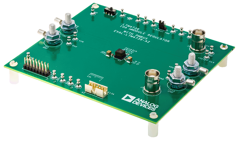
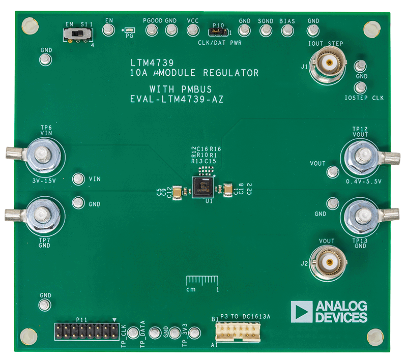
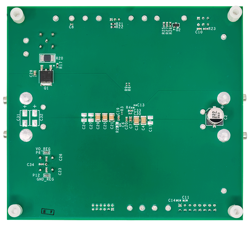
The EVAL-LTM4739-AZ evaluation board features the LTM®4739: a complete, high efficiency, high power-density, single 10A DC-to-DC step-down power μModule® (micromodule) regulator with PMBus interface. The LTM4739 is available in a 49-lead 6.25mm × 6.25mm × 5.07mm Ball grid array (BGA) package. Read the LTM4739 data sheet before using or making any hardware changes to the EVAL-LTM4739-AZ evaluation board.

The EVAL-LTM4739-AZ input voltage range is 3V to 15V, and the output voltage range is 0.4V to 5.5V. The maximum load current is 10A. The output voltage is adjusted through the feedback resistor divider or the PMBus VOUT_COMMAND (the factory default output voltage is 1V). The switching frequency range is 500kHz to 2MHz (factory default frequency is 500kHz), configured through the pin-strap resistor at the PGM1 or with PMBus commands. The resistor value at the PGM1 pin is also used to adjust the control loop compensation parameters. The resistor value at the PGM0 pin is used to configure the positive overcurrent (POC) protection triggering level and the factory default PMBus address (0x39h). The factory default POC protection sets the peak inductor current limit to 15A. At a high ambient temperature, the current output may need to be derated (Refer to the LTM4739 data sheet for more details).

EVAL-LTM4739-AZ
LTM4739: 15VIN, Single 10A Step-Down μModule Regulator with PMBus
EVAL-LTM4739-AZ Board Photo Angle View EVAL-LTM4739-AZ Board Photo Top View EVAL-LTM4739-AZ Board Photo Bottom View

Latest Discussions

No discussions on LTM4739 yet. Have something to say?

Start a Discussion on EngineerZone®

Recently Viewed