

ADPL31613
RECOMMENDED FOR NEW DESIGNSDual 1.3A, 1.2MHz Boost/Inverter in 3mm × 3mm DFN
Dual 1.3A, 1.2MHz Boost/Inverter in 3mm × 3mm DFN
- Part Models
- 1
- 1ku List Price
- Starting From $1.34
Overview
- 1.2MHz Switching Frequency
- Low VCESAT Switches: 380mV at 1.3A
- High Output Voltage: Up to 38V
- Wide Input Range: 2.4V to 16V
- Inverting Capability
- 5V at 630mA from 3.3V Input
- 12V at 320mA from 5V Input
- –12V at 200mA from 5V Input
- Uses Tiny Surface-Mount Components
- Low Shutdown Current: <2μA
- Low Profile (0.75mm) 10-Lead 3mm × 3mm Dual Flat No-Lead (DFN) Package
The ADPL31613 dual switching regulator combines two 38V, 1.3A switches with error amplifiers that can sense to ground, providing boost and inverting capability. The low-VCESAT bipolar switches enable the device to deliver high-current outputs in a small footprint. The ADPL31613 switches at 1.2MHz, enabling the use of tiny, low-cost, low-profile inductors and capacitors. High inrush current at start-up is eliminated by the programmable soft-start function, in which an external resistor-capacitor (RC) sets the current ramp rate. A constant-frequency current-mode pulse width modulation (PWM) architecture results in low, predictable output noise that is easy to filter.
The ADPL31613 switches are rated at 40V, making the device ideal for boost converters up to ±38V, and for SEPIC and flyback designs. Each channel can generate 5V at up to 630mA from a 3.3V supply, or 5V at 510mA from four alkaline cells in a single-ended primary inductor converter (SEPIC) design. The device can be configured as two boosts, a boost and inverter, or two inverters.
The ADPL31613 is available in a low-profile (0.75mm) 10-lead 3mm × 3mm DFN package.
APPLICATIONS
- Organic Light Emitting Diode (LED) Power Supply
- Digital Cameras
- White LED Power Supply
- Cellular Phones
- Medical Diagnostic Equipment
- Convertible ±5V or ±12V Supply
- Thin-Film Transistor (TFT)– Liquid-Crystal Display LCD) Bias Supply
- X Digital Subscriber Line (xDSL) Power Supply
Documentation
Data Sheet 1
User Guide 1
ADI has always placed the highest emphasis on delivering products that meet the maximum levels of quality and reliability. We achieve this by incorporating quality and reliability checks in every scope of product and process design, and in the manufacturing process as well. "Zero defects" for shipped products is always our goal. View our quality and reliability program and certifications for more information.
| Part Model | Pin/Package Drawing | Documentation | CAD Symbols, Footprints, and 3D Models |
|---|---|---|---|
| ADPL31613CPZ-RL | 10-Lead DFN (3mm x 3mm w/ EP) |
This is the most up-to-date revision of the Data Sheet.
Software Resources
Can't find the software or driver you need?
Request a Driver/SoftwareTools & Simulations
LTspice
Models for the following parts are available in LTspice:
- ADPL31613
LTspice® is a powerful, fast and free simulation software, schematic capture and waveform viewer with enhancements and models for improving the simulation of analog circuits.
Evaluation Kits
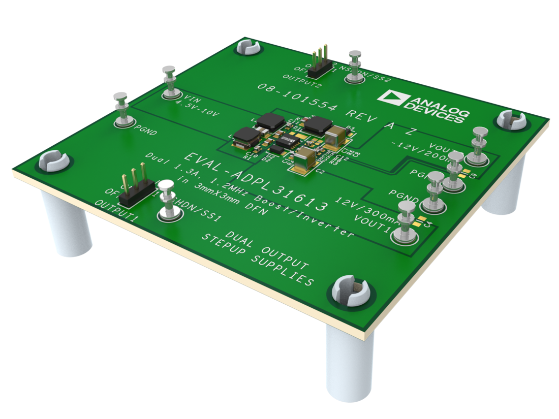
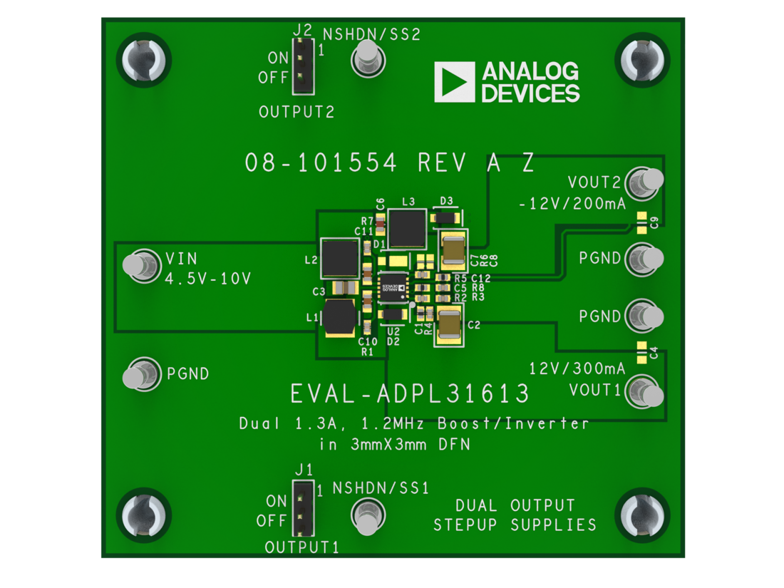
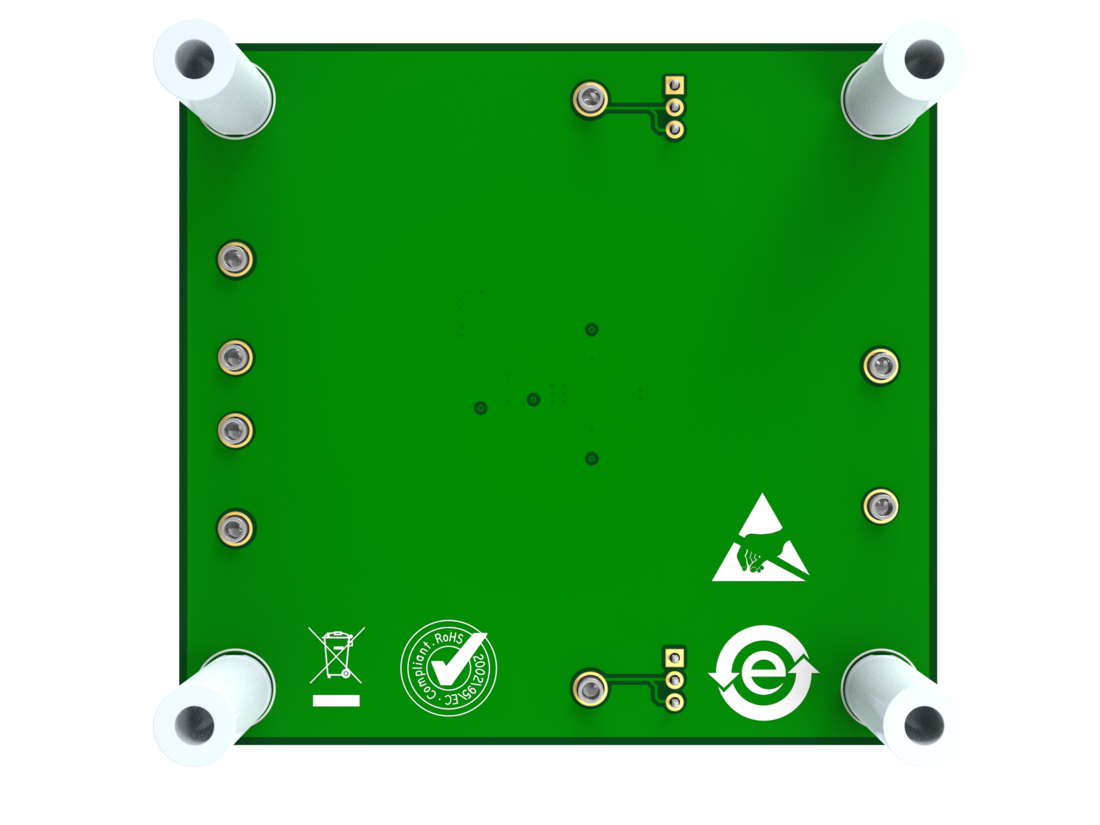
Evaluates: ADPL31613 in a ±12V Output Voltage Application
Resources
Latest Discussions
No discussions on ADPL31613 yet. Have something to say?
Start a Discussion on EngineerZone®