ADG1736
RECOMMENDED FOR NEW DESIGNSLow Voltage, 2.4Ω Dual SPDT Switch in 2mm × 2mm LGA Package
- Part Models
- 1
- 1ku List Price
- Starting From $1.74
Overview
- ±1.08V to ±2.75V dual supply
- +1.08V to +5.5V single supply
- Low on resistance 2.4Ω
- 16-lead, 2mm × 2mm LGA
- 1.8V and 3V JEDEC compliant logic
- Fully specified at +5V, +3.3V, +1.8V, and ±2.5V
- Rail-to-rail signal range
- −40°C to +125°C operating temperature range
The ADG1736 is an analog multiplexer containing two independently selectable single-pole, double throw (SPDT) switches and operates with a low-voltage single supply range from +1.08V to + 5.5V or a low-voltage dual supply range from ±1.08V to ±2.75V. An EN input is used to disable all of the switches.
The ADG1736 is designed for small size without compromising on performance. The 2mm × 2mm land grid array (LGA) package is ideal for a broad range of applications where area is a concern.
The ADG1736 has a low on resistance of just 2.4Ω and a rail-to-rail input signal range. Each switch conducts equally well in both directions when on. The digital control inputs are 1.8V and 3V JEDEC compliant for ease of use with microcontrollers and field programmable gate arrays (FPGAs).
APPLICATIONS
- Automated test equipment
- Data acquisition systems
- Medical equipment
- FPGA and microcontroller systems
- Audio and video signal routing
- Communications systems
- Relay replacement
Documentation
Data Sheet 1
User Guide 1
ADI has always placed the highest emphasis on delivering products that meet the maximum levels of quality and reliability. We achieve this by incorporating quality and reliability checks in every scope of product and process design, and in the manufacturing process as well. "Zero defects" for shipped products is always our goal. View our quality and reliability program and certifications for more information.
| Part Model | Pin/Package Drawing | Documentation | CAD Symbols, Footprints, and 3D Models |
|---|---|---|---|
| ADG1736BCCZ-RL7 | 16-Lead LGA (2 mm x 2 mm x 0.74 mm) |
Software Resources
Can't find the software or driver you need?
Request a Driver/SoftwareHardware Ecosystem
| Parts | Product Life Cycle | Description |
|---|---|---|
| LDO Linear Regulators 3 | ||
| ADP162 | PRODUCTION | Ultralow Quiescent Current, 150 mA, CMOS Linear Regulators |
| ADP7142 | RECOMMENDED FOR NEW DESIGNS | 40 V, 200 mA, Low Noise, CMOS LDO Linear Regulator |
| ADP7185 | RECOMMENDED FOR NEW DESIGNS |
-500 mA, Ultralow Noise, High PSRR, Low Dropout Linear Regulator |
| Parts | Product Life Cycle | Description |
|---|---|---|
| ADG736 | PRODUCTION | CMOS Low Voltage 2.5 Ω Dual SPDT Switch |
Tools & Simulations
LTspice
Models for the following parts are available in LTspice:
- ADG1736
IBIS Model 1
LTspice® is a powerful, fast and free simulation software, schematic capture and waveform viewer with enhancements and models for improving the simulation of analog circuits.
Evaluation Kits
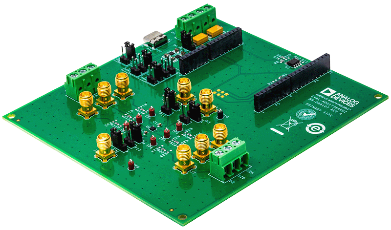
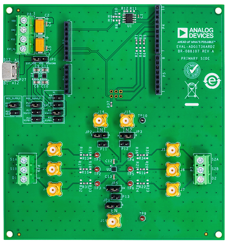
Evaluating the ADG1736, 2.4Ω Dual SPDT Switch
Resources
Latest Discussions
No discussions on ADG1736 yet. Have something to say?
Start a Discussion on EngineerZone®