

MAX77813
PRODUCTION5.5V Input, 2A, High-Efficiency Buck-Boost Converter
Industry's Best Transient Response Performance with High-Efficiency Across the Load Range
- Part Models
- 6
- 1ku List Price
- Starting From $0.93
Overview
- VIN Range: 2.30V to 5.5V
- VOUT Range: 2.60V to 5.14V (I2C Programmable in 20mV Step)
- Up to 2A Output Current in Boost Mode (VIN = 3.0V, VOUT = 3.4V, ILIM = High)
- Up to 3A Output Current in Buck Mode (ILIM = High)
- Up to 97% Peak Efficiency
- SKIP Mode for Optimal Light Load Efficiency
- 55μA (Typ) Low Quiescent Current
- 3.4MHz High Speed I2C Serial Interface
- Inductor Switching Current Limit Selection Pin
- Power-OK Output
- 2.5MHz Switching Frequency
- Protection Features
- Soft-Start
- Thermal Shutdown
- Overvoltage Protection
- Overcurrent Protection
- 2.13mm x 1.83mm, 20-Bump WLP
The MAX77813 is a high-efficiency step-up/step-down (buck-boost) converter targeted for single-cell Li+/Li-ion battery powered applications. The device maintains a regulated output voltage from 2.6V to 5.14V across an input voltage range of 2.3V to 5.5V. The device supports up to 2A of output current in boost mode and up to 3A in buck mode.
The device seamlessly transitions between buck and boost modes. A unique control algorithm allows high-efficiency, outstanding load, and line transient response.
Dedicated enable and power-OK pins allow simple hardware control. An I2C serial interface is optionally used for dynamic voltage scaling, system power optimization, and fault read-back. The device supports two inductor switching current limit options selected by the ILIM pin.
The MAX77813 is available in a 20-bump, 2.13mm x 1.83mm wafer-level package (WLP).
APPLICATIONS
- Single-Cell Li-ion Powered Applications
- Handheld Scanners, Mobile Payment Terminals, Security Cameras
- AR/VR Headsets
Documentation
Video 1

ADI has always placed the highest emphasis on delivering products that meet the maximum levels of quality and reliability. We achieve this by incorporating quality and reliability checks in every scope of product and process design, and in the manufacturing process as well. "Zero defects" for shipped products is always our goal. View our quality and reliability program and certifications for more information.
| Part Model | Pin/Package Drawing | Documentation | CAD Symbols, Footprints, and 3D Models |
|---|---|---|---|
| MAX77813EWP+ | Wafer-Level Package 5x4 Bump, Full Array | ||
| MAX77813EWP+T | Wafer-Level Package 5x4 Bump, Full Array | ||
| MAX77813EWP33+ | Wafer-Level Package 5x4 Bump, Full Array | ||
| MAX77813EWP33+T | Wafer-Level Package 5x4 Bump, Full Array | ||
| MAX77813EWP45+ | Wafer-Level Package 5x4 Bump, Full Array | ||
| MAX77813EWP45+T | Wafer-Level Package 5x4 Bump, Full Array |
| Part Models | Product Lifecycle | PCN |
|---|---|---|
|
Feb 21, 2025 - 2453N ASSEMBLY |
||
| MAX77813EWP+ | PRODUCTION | |
| MAX77813EWP+T | PRODUCTION | |
| MAX77813EWP45+ | PRODUCTION | |
| MAX77813EWP45+T | PRODUCTION | |
This is the most up-to-date revision of the Data Sheet.
Software Resources
Can't find the software or driver you need?
Request a Driver/SoftwareTools & Simulations
ADI Power Studio™ Designer
ADI Power Studio™ Designer is the next-generation tool for IC-level, power supply design, guiding engineers to faster, validated solutions.
Learn MoreSoftware Development 1
SIMPLIS Models 1
Evaluation Kits
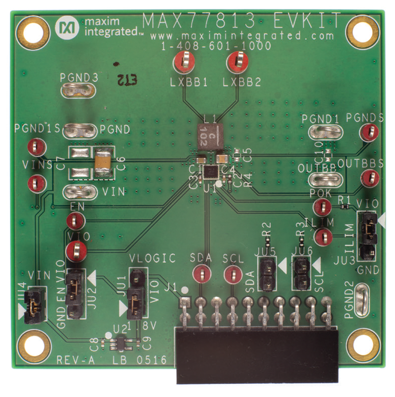
Evaluation Kit for the MAX77813
Resources
Latest Discussions
No discussions on MAX77813 yet. Have something to say?
Start a Discussion on EngineerZone®