思想领导力


 关闭详情
关闭详情
C频段并置,降低风险的策略
频谱越多,干扰越多
无线革命开始于大约30年前,当时只有少数几个频段,并且大部分限制在900 MHz以下,通常每个国家和地区有一到两个频段。如今,频段数量呈指数级增长,仅FR1中就有76个LTE和5G频段。为了找到可用的频谱,频率不断升高。美国最近的C频段(3700-3980MHz)拍卖活动也凸显了这一点。目前行业正从购买频谱转向建设网络,而从射频角度来看,C频段与以前的部署大不相同。特别是,当C频段的某些无线电架构与遗留无线电并置时,相关干扰可能导致站点管理遭遇挑战。
宏基站塔日益增多,这些塔必须承载巨大重量并承受超强风载荷。C频段的初始部署很可能会重新使用这些站点,这意味着C频段无线电将与LTE和GSM设备并置一地。考虑一下,在塔顶,一台无线电设备的发射功率可能为100W或更高,而距离仅一米(或更近)的另一台无线电设备接收信号的功率可能低于100 nW,即接收功率约为发射功率的100亿分之一。之前也是如此,但C频段的频率较高,导致复杂性提高,即混叠或信号干扰的可能性增加了。
混叠、阻塞和奈奎斯特区
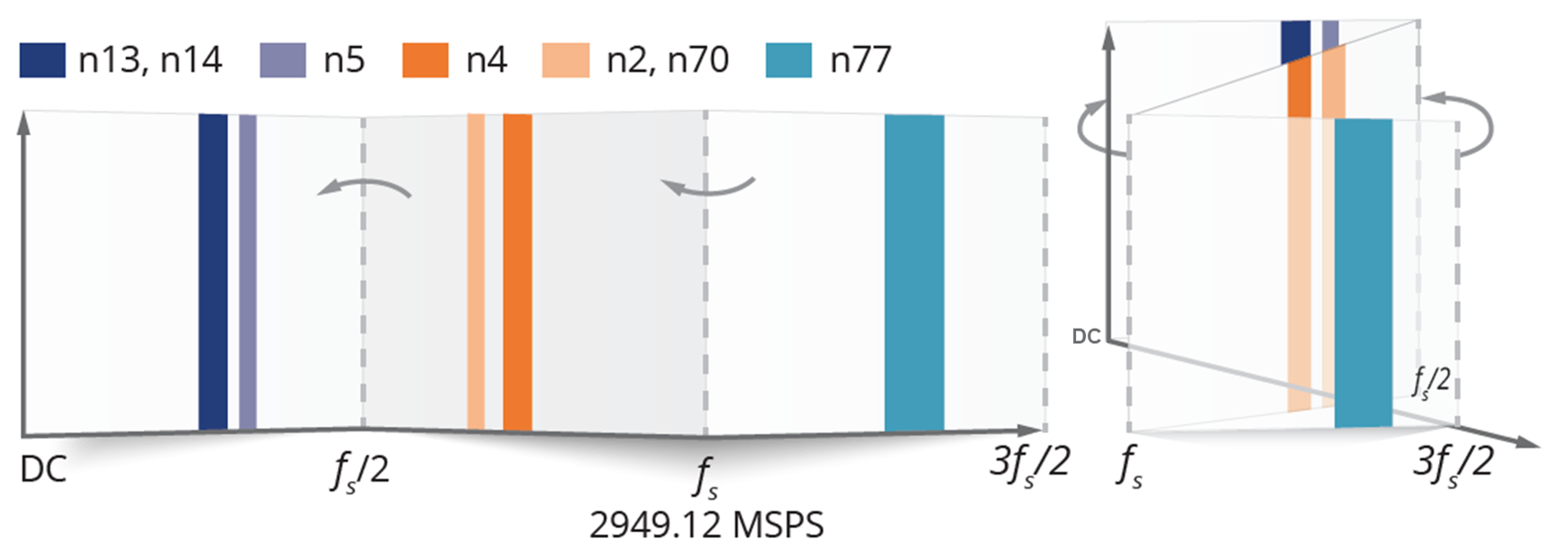
还记得信号处理课上的奈奎斯特区吗?总结一下采样标准,奈奎斯特区将频谱划分为多个间隔为Fs/2且均匀分布的区域。每个奈奎斯特区包含所需信号频谱的一个副本或其镜像(称为混叠)。采样速率上下等量的信号在模数转换器(ADC)输出端相互折叠形成混叠。
无线电通过滤波器抑制来自其他无线电的干扰。无线电单元中核心射频架构的选择使这个问题变得难以解决,甚至无法解决。在这种情况下,“解决困难”意味着花费高昂成本。如果无线电架构使用特定的采样速率,对混叠的敏感度就会增加,导致滤波器更重、更昂贵。遗憾的是,敏感度问题可能直到设计周期的后半段,即做出核心架构决策之后才能发现。
零中频无线电通过仅转换目标频段来减少并置问题,而直接射频架构则转换所有带宽并使用滤波器来捕获目标频段。常见的直接射频模数转换采样速率在3GHz到4GHz之间。对于C频段,这意味着在所需频段附近存在奈奎斯特边界,因此采样速率上下的等量信号会在ADC输出端相互折叠。所有可能在所需信号之上混叠的频率都需要进行充分滤波,以免影响接收器的灵敏度。这些频率的信号越强,滤波器就越大、越贵、越重。较糟糕(同时也是成本较昂贵)的情况是干扰信号源是并置的变送器。事实证明,当使用基于这些ADC的器件时,C频段频率和一些常用的FDD频段会相互干扰。
底线
您需要开始设计时就知道如何解决无线电架构并置问题,并且必须要了解所选择的无线电架构和其中包含的采样速率。回顾:
- 滤波器可能占C频段无线电重量的30%到40%。与配合ADI公司ZiF无线电使用的滤波器相比,混叠问题可能会使其重量增加50%。
- 已经安装的无线电也可能存在风险,因为混叠问题是相互的。也就是说,在同一塔上部署C频段无线电,可能会导致已经部署的2GHz左右无线电停止工作。
- 此外,过去的表现并不能保证未来会有同样的结果。新的频谱不断被分配。对混叠较为敏感且目前正常工作的无线电,将来可能无法工作。
欲了解更多信息,请访问: analog.com/5G。