Micropower, Precision Current Sense Amplifier Operates from 2.5V to 60V
Introduction
The LT1787 is a precision, high-side current sense amplifier designed for monitoring of the current either into or out of a battery or other element capable of sourcing or sinking current. The LT1787 features a miniscule 40µV (typical) input offset voltage with a 128mV full-scale input voltage. (The part is generally used at ±128mV full-scale, although it is specified for 500mV minimum full-scale.) This translates to a 12-bit dynamic range in resolving currents. A hefty 60V maximum input voltage specification allows the part to be used not only in low voltage battery applications but also in telecom and industrial applications where higher voltages may be present.
The device is self-powered from the supply that it is monitoring and requires only 60µA of supply current. The power supply rejection ratio of the LT1787 is in excess of 130dB.
The LT1787 allows the use of a user-selectable sense resistor, the value of which depends on the current to be monitored. This allows the input voltage to be optimized to the 128mV value, maximizing dynamic range. The part has a fixed voltage gain of eight from input to output.
Additional LT1787 features include provisions for input noise filtering (both differential and common mode) and the ability to operate over a very wide supply range of 2.5V to 60V. The part is available in both 8-lead SO and MSOP packages.
Operation of the LT1787
Figure 1 shows a function diagram of the LT1787 integrated circuit. When current is flowing from VS+ to VS–, a sense voltage of VSENSE = ISENSE • RSENSE is generated. Because amplifier A1’s positive and negative inputs are forced equal by feedback, VSENSE also appears across the RG side with the higher VS potential. Hence, for the situation where VS+ is greater than VS–, VSENSE appears across RG2A and RG2B. This current flows through Q2 and becomes the output current, IOUT. Q1 is kept off by the amplifier and does not contribute to IOUT.
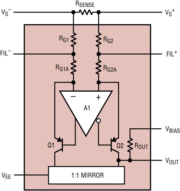
Figure 1. LT1787 function diagram.
For split-supply operation, where VS+ and VEE range from ±2.5V to ±30V; with VBIAS at ground, VOUT becomes (IOUT • ROUT). In this case, and for the above described direction of sense current, VOUT is positive or “above” VBIAS; thus Q2 is sourcing current.
When current flows from VS– to VS+, input VS– is at a higher potential than VS+, so VSENSE will appear across RG1A and RG1B. The current, IOUT = VSENSE/(RG1A + RG1B), will be conducted through Q1, while Q2 remains off. IOUT then duplicates itself through a one-to-one current mirror at VOUT. VOUT is negative or “below” VBIAS; Q1 sources current and the mirror sinks the current at the VOUT node.
The output voltage across ROUT is related to the input sense voltage by the following relationships:


Selection of RSENSE
Maximum sense current can vary for each application. To sense the widest dynamic range, it is necessary to select an external sense resistor that fits each application. 12-bit dynamic range performance can be achieved regardless of the maximum current to be sensed, whether it is 10mA or 10A. The correct RSENSE value is derived so that the product of the maximum sense current and the sense resistor value is equal to the desired maximum sense voltage (usually 128mV). For instance, the value of the sense resistor to sense a maximum current of 10mA is 128mV/10mA = 12.8Ω. Since the LT1787 is capable of 12-bit resolution, the smallest measurable current is 10mA/4096 counts = 2.44µA/count. In terms of sense voltage, this translates to 128mV/4096 = 31.25µV/count. Other current ranges can be accommodated by a simple change in value in the sense resistor. Care should also be taken to ensure that the power dissipated in the sense resistor, IMAX.2 • RSENSE, does not exceed the maximum power rating of the resistor.
Application Circuits
Dual-Supply, Bidirectional Current Sense
Figure 2 shows the schematic diagram of the LT1787 operated with dual supplies. This circuit can sense current in either direction, positive current flow being from VS+ to VS–, where the output ranges from 0V to 1.024V for VSENSE = 0mV to 128mV, and negative current flow being from VS– to VS+, where the output varies from 0V to –1.024V for VSENSE = 0mV to –128mV. Figure 3 shows the output voltage versus VSENSE for this configuration.
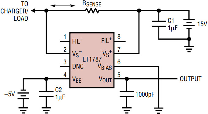
Figure 2. Split-supply, bidirectional operation.
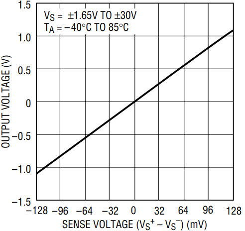
Figure 3. VOUT vs VSENSE in bipolar mode.
Operation with Bias
If a negative supply is not available, a voltage reference may be connected to the VBIAS pin of the LT1787. The value of the reference is not critical, it simply biases the output of the part to a new “zero” point (for VSENSE = 0V); zero is now at VBIAS = VREF, which, for the case of Figure 4, is equal to 1.25V. This configuration can be used for both unipolar and bipolar current sensing, with VOUT ranging either “above” or “below” VBIAS, depending on the direction of the current flow. This can be seen from the graph shown in Figure 5. (Note that the reference must be able to both source and sink current from the VBIAS pin—refer to the block diagram in Figure 1.)
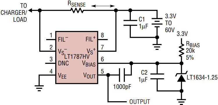
Figure 4. Bidirectional operation with a reference.
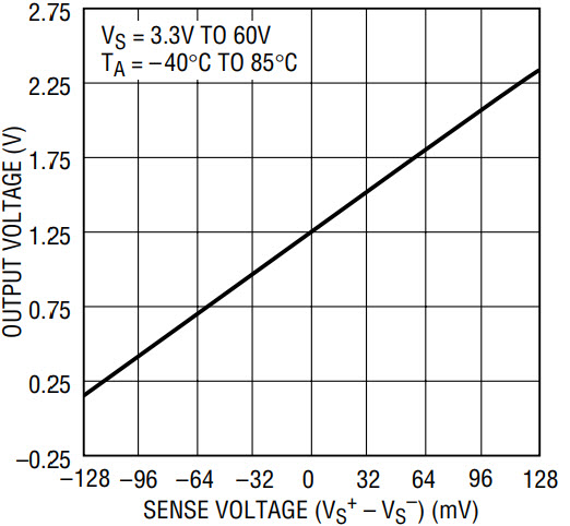
Figure 5. VOUT vs VSENSE in bipolar mode.
Operation with a Buffer
Figure 6 uses a rail-to-rail op amp, the LT1495, as an I/V converter to buffer the LT1787’s output. The LT1634-1.25 reference is used to bias the LT1787’s output so that zero current is now represented by a 1.25V output. This allows the device to monitor current in either direction while the circuit operates on a single supply. This also allows lower voltage operation, since VOUT of the LT1787 is held constant by the op amp. Figure 7 shows input current versus output counts (from the LTC1404 A/D converter), showing excellent linearity.
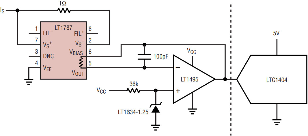
Figure 6. Operation with a buffer.
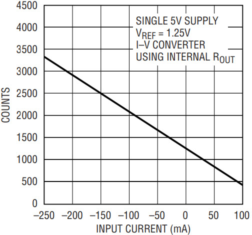
Figure 7. Output counts vs input current for Figure 6’s circuit.
Single-Supply Current Sense
The circuit in Figure 8 provides good accuracy near full-scale, but has a limited dynamic range. In this circuit, the LT1787 is operated from a single supply of 2.5V minimum to 60V maximum. Current is allowed to flow through RSENSE in both directions but is measured in a single direction only, with current flow from VS+ to VS–. In this connection, VBIAS and VEE are grounded. The output voltage (VOUT ) of the LT1787 for this circuit is equal to 8 • VSENSE, for VSENSE = VS+ – VS– = 0mV to 128mV. The dynamic range limits of this circuit can be seen in the graph shown in Figure 9.
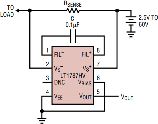
Figure 8. Output voltage referred to ground—unidirectional sensing mode.
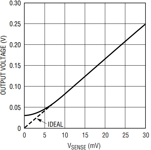
Figure 9. Expanded scale of VOUT vs VSENSE, unidirectional current sensing mode.
Operation with an A/D Converter
Figure 10 shows the details of an LT1787 connected to a LTC1404 12-bit serial A/D converter. Details of the circuit are similar to those shown previously in Figures 2 and 8 and in the text detailing these circuits. The main difference in the applications is that the circuits in Figures 2 and 8 provide an analog output voltage proportional to the current, whereas the circuit shown in Figure 10 digitizes that analog voltage to provide a digital output. Figures 11 and 12 show the output of the LTC1404 A/D converter. The data in Figure 11 was collected with VEE operated from –5V; in other words, both the LT1787 and the LTC1404 used a negative supply of –5V. Similarly, the data in Figure 12 was taken with VEE connected to ground.
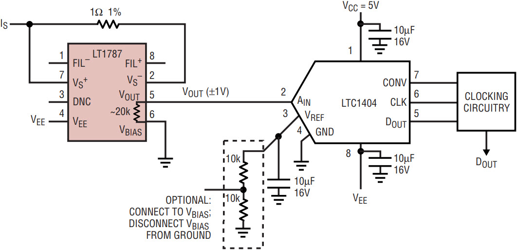
Figure 10. Connection to an A/D converter (current-to-counts converter).
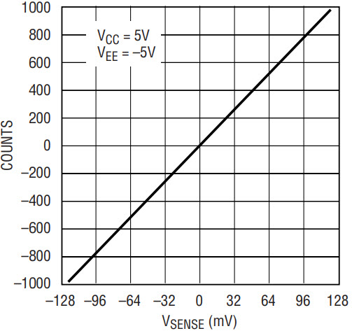
Figure 11. LT1787 input to LTC1404 ADC.
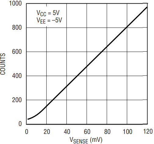
Figure 12. LT1787 input to LTC1404 ADC—single supply.
Connecting the optional section of the schematic (still operating the circuit from a single supply) allows the A/D’s reference to “bias up” the LT1787 exactly as shown in Figure 5. Of course, the graph of the output would then be recast as similar to Figure 11 (counts versus VSENSE).
Auto Shutdown Linear Regulator
Figure 13 shows the details of a linear regulator with high-side current sensing and latched shutdown capability. The circuit shuts down power to the load when the current reaches its overcurrent trip point. Power can then be restored only by cycling the main power off and on again. This circuit features the LT1787 and the LTC1440 precision comparator with on-chip reference. The LT1528 is a 3A low dropout linear regulator with shutdown.
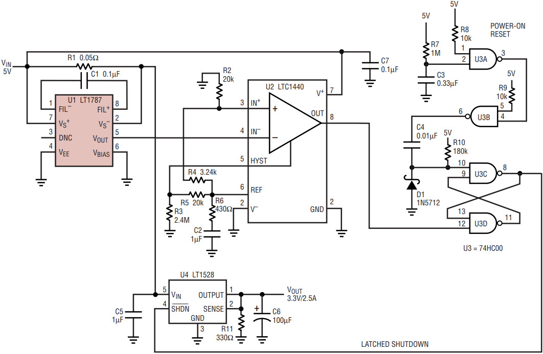
Figure 13. LT1787 auto shutdown with latch.
The circuit uses the LT1787, U1, as a precision current sensor; the gain of the LT1787 allows the use of a 0.05Ω sense resistor, which dissipates a mere 0.312W of power. The LTC1440 ultralow power comparator, U2, with its internal reference, is used as a precision trigger, followed by a 74HC00 connected as an RS flip-flop (U3C and U3D) to latch the error condition until power is removed and reapplied. The other two NAND gates are used to provide a power-on reset of the RS flip-flop. The 1M resistor, R7, and the 0.33µF capacitor, C3, at pin 2 of U3A provide a long enough time constant to properly initialize the flip-flop.
As shown, the circuit’s trip point for shutdown is just under 2.5A. This may be changed by altering the value of current sense resistor R1. Consult the LT1787 data sheet for details on how to alter this resistor to sense different current ranges.
Battery Fuel Gauge
The industry standard method for gauging battery charge is to keep track of the endpoints, the full charge and discharged states, and, in between, to measure how much discharge has occurred since the last full charge (and vice versa). In an automobile, this would be analogous to having only a “full” reading and an “empty” reading on the gas tank, and, in between, to keep track of mileage. Applying this strategy to batteries is called “Coulomb-counting”; it is achieved by measuring (and numerically accumulating in a microcontroller) the current flow from the battery over time. Keeping track of the history of battery currents and voltages allows the present state of the battery charge to be determined. Hence the need for an accurate current sense amplifier like the LT1787.
Figure 14 shows a schematic for measuring battery current using the LT1787 and measuring battery voltage using the micropower LT1635 with 200mV internal reference. The LT1787 is configured for single-supply, bidirectional operation, with the 2.0V reference coming from U2B, the LT1635 (created by amplifying its internal 200mV reference by a gain of ten.) Note that the reference voltage is fed to the ADC, so its absolute value is not critical, except in that it will form the center point for the battery voltage measurement and will thus determine the valid battery input voltage range. Resistors R1 and R2 form a divide-by-five, bringing the battery voltage down from ~10.8V to ~2.1V to put it within the input range of a downstream ADC. Op amp U2A with resistors R3 and R4 level shift this by the reference voltage and apply a gain of five. If a 12-bit ADC with a 5V reference is used, the following equations apply:

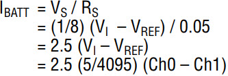
where Ch0, Ch1 and Ch2 are in counts from 0 to 4095.
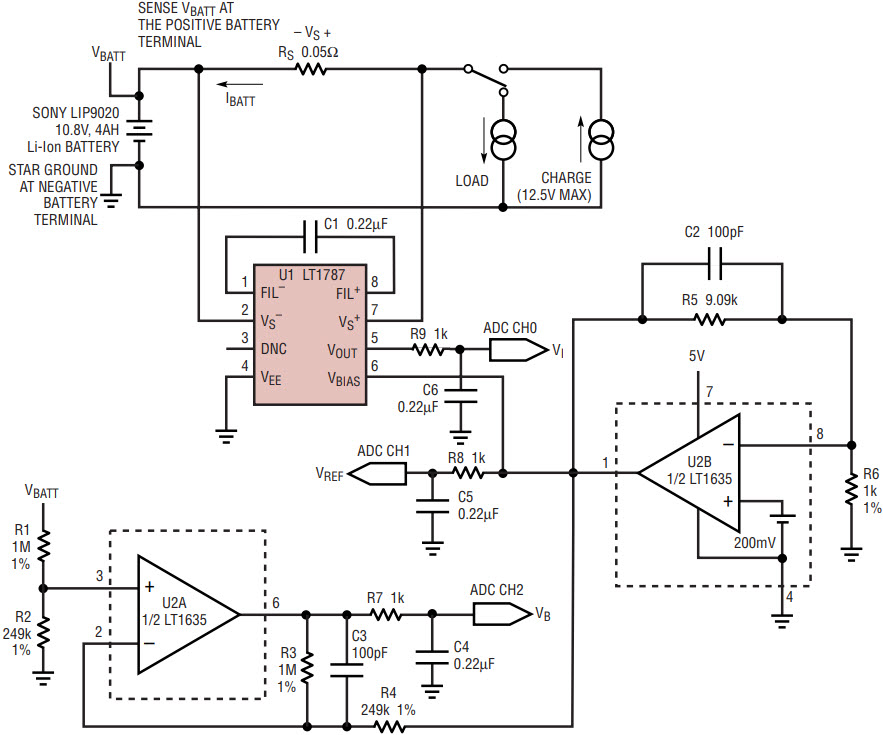
Figure 14. Battery “fuel gauging” system.
Figure 15 shows a typical discharge and charge cycle for a 10.8V, 4A-hour Li-Ion battery.
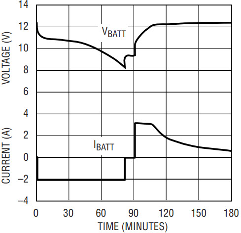
Figure 15. Discharge and charge cycle of a 10.8V Li-Ion battery.
Conclusion
The LT1787 high-side current sense amplifier provides an easy-to-use method of sensing current with 12-bit resolution for a multiplicity of application areas. The part can operate to 60V, making it ideal for higher voltage topologies such as might be used in telecom or industrial applications. Additionally, the part can find homes in battery-powered, handheld equipment and computers, where the need for gauging the amount of current consumed and/or the amount of charge remaining in the battery is critical.


