
Using Available Tools to Evaluate a Power Supply the Easy Way
Key Takeaways
|
Abstract
This article summarizes how power supplies are developed with the help of modern development tool chains. After a power supply has been designed, hardware needs to be evaluated. New tools such as those that create Bode diagrams, a compensation probe, and an efficiency measurement device make the evaluation of power supply hardware simple and accurate.
Introduction
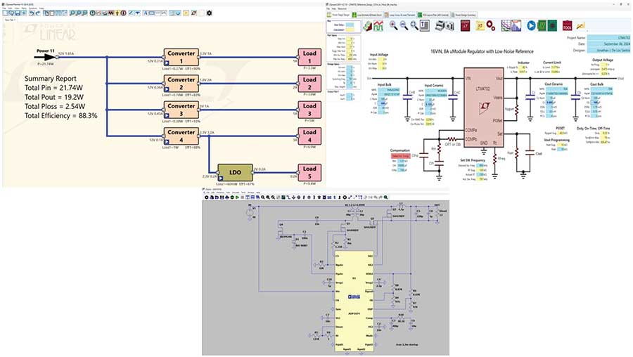
Power supplies are a necessary evil for most electronic circuits. They are absolutely necessary, but usually only have a supporting function. Because of this, essential development work should focus on the core function of a circuit and not on the creation of a suitable power supply. Designers already have a variety of calculation and simulations tools that can help them with power supply development. Many of these development tools are offered by the manufacturers of power supply ICs and are free of charge. The following is a list of the different possible tools for power supply development. See Figure 1.
LTpowerPlanner®
The LTpowerPlanner tool is used to create architectures of power supplies. Usually several supply voltages are required in a system, not just a single-supply voltage. The first step in power supply design is to create an appropriate architecture. Should all required voltages be generated directly from the available voltage source or must an intermediate (DC link) voltage be generated? LTpowerPlanner helps to create an optimized architecture of the power supply.
LTpowerCAD®
After the architecture has been created, individual voltage converters must be designed. Calculation tools such as LTpowerCAD are suitable for this purpose. The requirements such as input voltage range, output voltage, and output current are entered into these tools. The tool performs circuit calculations and suggests an optimized circuit.
LTspice®
After the successful calculation of the power supply, the circuit is simulated with LTspice. In this simulation, the control loop stability can be optimized and additional circuit parts can be added to the circuit calculated with LTpowerCAD.
After successful development of the power supply, it must be tested. Even the best circuit calculations and simulations are only as good as the formulas and models used. Some parasitic influences cannot be easily predicted and must be evaluated in the lab. This requires a variety of instrumentation equipment and a lot of time for the work in the lab.
The main evaluations in the lab are load transient tests, stability and control loop measurements, and efficiency measurements.
LTpowerAnalyzer™
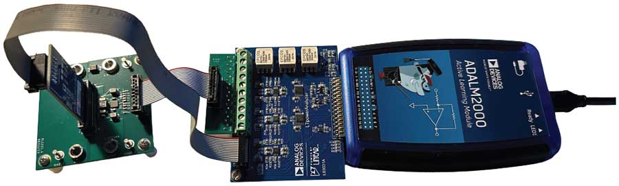
To facilitate not only the design of a power supply, but also the evaluation work in the lab, Analog Devices has developed the LTpowerAnalyzer. It is designed to measure optimal Bode diagrams of the control loop in a simple way. An injection transformer is integrated, with which a small, adjustable, sine wave signal is injected into the control loop over a wide frequency range. The change in amplitude through the control loop shows the gain at different frequencies and the phase offset provides information about the phase margin.
After some minor prework on the power supply to be tested (device under test (DUT)), the LTpowerAnalyzer can be connected and a Bode plot of the control loop created by the supplied software within minutes. See Figure 2.
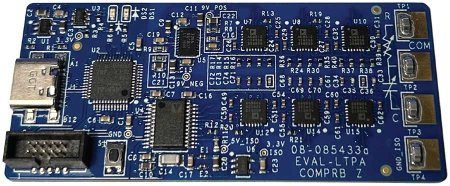
If the Bode diagram measurement does not meet the expectations, the compensation network must be adjusted, which essentially consists of a capacitor and resistor connected to the compensation pin. This pin is called Ith, Vc, or Vcomp. Usually, extensive soldering work is required to solder in different combinations of compensation capacitors and resistors. The EVAL-LTPA-COMPRB board, which is also available to order, allows different compensation settings to be selected with the software. The board is connected to the compensation pin of the power supply instead of the compensation components. The EVAL-LTPA-COMPRB is connected to the PC via USB. The included software allows a user to choose between many different compensation settings and then create a Bode diagram measurement with the LTpowerAnalyzer. This procedure helps to optimize the power supply circuit and saves a lot of time compared to the conventional method of soldering in and out individual compensation components. See Figure 3.
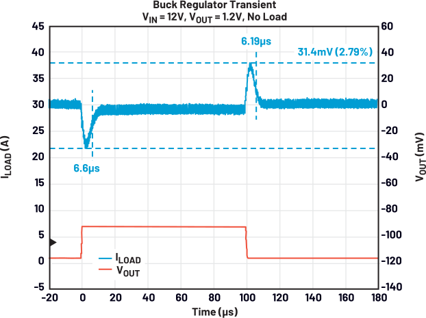
In addition to a Bode diagram measurement of the power supply, the LTpowerAnalyzer can be used to perform load transient tests up to 100A (Figure 4). And all this without the need for an expensive electronic load in the lab. Small, controllable load boards are part of the LTpowerAnalyzer kit and are connected to the output of the power supply to be tested. The software initiates adjustable load jumps and displays the resulting change in the output voltage.
Another important test for power supplies is the efficiency of the voltage conversion. This is important to anticipate the heating of an appliance so that the right cooling measures can be taken. This is needed especially for operation at warm ambient temperatures. High efficiency also makes sense in terms of energy savings. Thus, an efficiency measurement of a power supply is mandatory. Highly accurate digital multimeters (DMMs) can be used for this purpose. These are often expensive and measurement results must be read individually for each measuring point during efficiency measurements. Specialized labs for power supplies sometimes have a measurement setup in place in which the individual voltage and current measurement systems communicate with each other and deliver complete efficiency curves on a PC. However, such systems must first be purchased and then operated.
With the new EVAL-LTPA-RL2000, an efficiency measurement of a power supply can easily be carried out in the shortest possible time. The RL2000 includes all the necessary equipment for high-precision efficiency measurements. Two voltage probing systems with a measuring range of ±125V and a resolution of 1mV (accuracy 0.025% reading + 0.01% range). An electronic load is also built into the RL2000 to allow load currents of up to 30A. These load currents can be dynamically modified to create an efficiency curve over a wide load range.
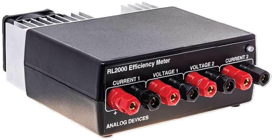
The RL2000 is connected to a computer via USB and the LTpowerAnalyzer software is used to adjust settings and create efficiency charts.
The maximum power of this setup for efficiency measurement is 150W at the output. If higher power is required, two RL2000 kits can be used, which can be operated together up to 300W.
In the low-power range, the RL2000 offers very high accuracy and the ability to calculate leakage currents of the measuring system and instruct the software to remove these leakage currents from the results. This means that power supplies in the nanoampere range can also be measured with high precision. This is particularly important for circuits from the energy harvesting sector.
Conclusion
Evaluating a power supply can take a lot of time and expensive measurement systems. Both the time spent and the investment in measurement systems can be drastically reduced by using these optimized tools from ADI: LTpowerAnalyzer, COMPRB (compensation probe), and RL2000 to measure efficiency. These three measuring devices work together with the LTpowerAnalyzer software, which is available free of charge. The operation is simple and the measurement results are accurate.