概览
设计资源
设计与集成文件
- Schematic
- Bill of Materials
- Gerber Files
- Allegro Layout Files
- Assembly Drawing
评估硬件
产品型号带"Z"表示符合RoHS标准。评估此电路需要下列选中的电路板
- EVAL-CN0532-EBZ ($101.52) IEPE Compatible Wideband MEMS Vibration Sensor
- EVAL-XLMOUNT1 ($115.06) Mechanical Mounting Block for MEMs Vibration Sensors
优势和特点
- Industry Standard IEPE Interface
- Wideband MEMs Accelerometer
- Direct Replacement for Piezo Sensors
参考资料
-
CN0532 User Guide2020/5/8WIKI
-
 CN0549 - CbM开发平台2025/9/5
 -
 CN0549 - CbM Development Platform2025/9/5
-
Condition Based Monitoring (CbM) using MEMS Accelerometers2022/3/23
-
状态监控(CbM)开发平台,从振动检测到算法开发2021/4/22
电路功能与优势
Condition-based monitoring (CbM) is one form of predictive maintenance that uses sensors to assess status of equipment overtime while the equipment is operating. The collected sensor data can establish baseline trends, such as, diagnose or even predict failure. Utilizing CbM, maintenance is performed when needed as opposed to the conventional periodic preventive maintenance model, saving both time and money.
Vibration monitoring is a common type of CbM measurement because changes in vibration trends are potentially indicative of wear or other failure modes. To measure vibration data, high bandwidth (10 kHz and more), ultralow noise (100 µg/√Hz or lower) piezoelectric sensors were historically used to satisfy these requirements. The established sensor interface for piezo sensors is integrated electronics piezoelectric (IEPE), as a result, IEPE has become a de facto interface in CbM vibration ecosystem.
With recent advancements in the microtechnology processes and fabrication techniques, MEMS accelerometers have caught up with piezoelectric sensors low noise levels and supersede in other many specifications, such as dc to low frequency response, thermal stability, shock resistance and recovery, and cost. The output of MEMS sensors, however, are either conventional 3-wire analog (ground, power, and signal) or digital if integrated with an ADC. Neither output are directly compatible with IEPE, the preferred CbM industry sensor interface.
This reference design enables a direct piezoelectric sensor IEPE replacement with benefits of high bandwidth, ultralow noise MEMS accelerometers. This circuit allows customers to easily evaluate a MEMS accelerometer for CbM applications.
电路描述
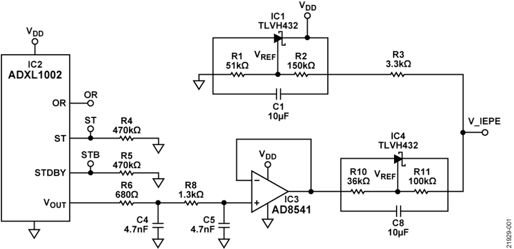
The circuit shown in Figure 1 demonstrates a MEMS accelerometer vibration sensing solution with included IEPE-compatible interface circuitry at 12.5 V bias and 4 mA current consumption.


EPE Protocol and Interface
The IEPE interface is a 2-wire protocol, signal and ground. An instrument, such as data logger, supplies power via the signal line to the vibration sensor as current with an arbitrary voltage, typically between 10 V to 30 V. Because the signal line is supplied by a current source, the sensor device can modulate the acceleration data on the voltage rail. Therefore, the single wire can be used for both the power supply and the modulated output voltage of the sensor. Figure 2 shows an example of the IEPE output with a bias voltage of 12 V and a full-scale range (FSR) swing of ±2 V.


Figure 3 shows the basic operation of the circuit. Regulator A supplies current to all elements. Regulator B adds dc offset (approximately 9.5 V) to the buffered output of the ADXL1002 (2.5 V ± 2 V) which gives enough compliance to the signal line (output voltage (V_IEPE) = 12 V ± 2 V). Because the voltage level on the signal line is always higher than 5 V, the shunt regulator (Regulator A) can generate a stable VDD (5 V) to power both the ADXL1002 and the AD8541.
The signal line current must not exceed 4 mA (the most common industry norm) and supply enough current to power the shunt regulators, buffer amplifier, and sensors for the whole sensor output swing, which is the primary constraint when choosing shunt regulators. The buffer amplifier sinks current from Regulator A and must have a high slew rate to cover ±2 V swing at 50 kHz. The AD8541 buffer satisfies this high slew rate requirement and also has an ultra-low, 100 µA quiescent current.
The supply voltage and Resistor R3 determines the shunt regulators current. The current and voltage are budgeted as follows:
- The V_IEPE range is fixed, 12 ± 2.5 V. The valid output range of the ADXL1002 is 2.5 V ± 2 V, but it has an additional ±0.5 V headroom drive capability without signal integrity. Therefore, for minimum and maximum current calculation, consider the maximum possible swing.
- Regulator A (IC1) must supply enough current to the sensor (IC2) and the buffer (IC3) at the lowest V_IEPE, that is, 9.5 V and (V_IEPE − VDD)/R3 > (IC2 and IC3 consumption) + (100 µA (maximum) minimum cathode current of IC1). Therefore, R3 is set to 3.3 kΩ. (V_IEPE − VDD)/R3 = 1.36 mA.
- When V_IEPE is at its highest (14.5 V), R3 consumes the highest current. (V_IEPE − VDD)/R3 = 2.88 mA. When the supply current from the data logger is 4 mA, the remainder of 1.12 mA is the minimum value of the cathode current that goes through Regulator B (IC4). The minimum cathode current of the IC4 (TL432B) is 1 mA (maximum). Therefore, IC4 is still operational.
The previous scenario allows containment of the total current consumption to the recommended 4 mA supply current from the data acquisition system.
Shunt regulators are carefully chosen to achieve high signal-tonoise ratio (SNR) while the regulators consume low current on the cathode. The noise of Regulator B directly affects the output, which has a dominant effect on the SNR. Note that, IC4 displays the lowest noise. However, its cathode current is relatively high (1 mA maximum). To maintain the total current below 4 mA, an IC2 was selected with a cathode current as low as 100 µA, which has the second best noise performance in the design.
MEMS Vibration Sensors Advantages
The ADXL1002 is an industry leading ultralow noise and wideband MEMS accelerometer. The noise spectral density of the ADXL1002 is 25 µg/√Hz and its 3 dB bandwidth is 11 kHz with sensor resonance frequency of 21 kHz. The noise and bandwidth is comparable with a piezoelectric sensor while the ADXL1002 provides superior performance in temperature sensitivity, dc to low frequency response, phase response (and thus, group delay), shock tolerance, and shock recovery. The sensor has a linear (within ±0.1% FSR) measurement range of ±50 g, which is large enough to support the majority of CbM applications. With the LFCSP package, it is easy to integrate the ADXL1002 circuitry as opposed to conventional piezoelectric sensors.
The ADXL1002 (and other Analog Devices, Inc., MEMS accelerometers) provide a low cost, high performance sensing solution for CbM applications with superior long-term reliability. All of which is required when adopting CbM technologies in the push towards Industry 4.0.
常见变化
This circuit can accommodate variations for different applications. The EVAL-CN0532-EBZ is based on the ADXL1002, with a sensor resonance frequency of 21 kHz. However, the same circuit can be used as an IEPE compatible interface for other sensors in the MEMS accelerometer family. Note that based on the sensor resonance frequency, select the low-pass filter cutoff frequency accordingly.
The AD8541 is configured as a zero gain buffer in this design. Therefore, the output swing of the sensor and the IEPE interface are the same. In another variation, however, to make the sensitivity scale of V_IEPE according to the piezoelectric sensor replacement device, or any other design requirements, adjust the gain of the AD8541 accordingly. Employ careful consideration when selecting the gain resistance so that the output current requirement of the sensor, regulators, and buffer is also met.
电路评估与测试
A brief description of how to set up the circuit and mechanical mounting, the methods to read output, and what to expect is given in the following subsections. For a complete description of the hardware, see the CN0532 User Guide.
Functional Block Diagram
Figure 4 shows the functional block diagram of the circuit. The solid line, black arrows depict the signal path and the dotted line, black arrows show the current supply path to power the circuit.
Figure 4. Block Diagram of the Vibration Sensing System with IEPE Interface.
Equipment Needed
The following equipment is needed:
- IEPE-compatible vibration measurement equipment, such as the LMS SCADAS from Siemens and the CompactDAQ from National Instruments
- Shaker table or vibration source
- Aluminum block (EVAL-XLMOUNT1)
- Coax cable or properly shielded wires
- The EVAL-CN0532-EBZ
Getting Started
The basic steps for understanding and recreating the test setup follow:
- Solder a coaxial or shielded cable to the printed circuit board (PCB).
- Connect the other end to an IEPE-compatible vibration measurement equipment such as the LMS SCADAS from Siemens or the CompactDAQ from National Instruments.
- Set the acceleration sensitivity (40 mV/G) on the vibration measurement equipment from Step 2 to taking data with the accelerometer sensors.
- The sensitivity scale of the ADXL1002 may slightly vary from part to part, and the ADXL1002 can be simply calibrated with gravity field or other reference sensors.
For complete details and setup information, see the CN0532 User Guide.
Power Supply Configuration
As previously discussed, the circuit must be supplied with a 4 mA current source, which can be provided by an IEPEcompatible vibration measurement setup or a simple current source. When using a simple current source, the supply line voltage is the output of the sensor.
Test Results
To verify performance of the circuit for vibration measurement applications, the circuit was tested in the Analog Devices vibration lab. The circuit is characterized for its frequency response, noise spectral density, and shock and group delay. Details and results of each test follows.
Frequency Response Measurements
The EVAL-CN0532-EBZ is attached to a shaker table through a mounting interface as shown in Figure 5, and the shaker table generates a controlled mechanical vibration from 100 Hz to 30 kHz, with a fixed 2 g acceleration. The output of the IEPE circuit and the reference vibration measurement (in this case, a laser doppler vibrometer) are recorded. The sensor output is calibrated for the accurate sensitivity scale factor using the low frequency peak amplitudes vs. the calibrated reference. Then, the output of the sine frequency sweep of the sensor is plotted as shown in Figure 6, which is consistent with the transfer function of the ADXL1002.


In this and any other high frequency vibration tests, mechanical signal path integrity is very important. In other words, from the source to the sensor, there must be no attenuation (due to damping) nor amplification (due to resonance) of the vibration signal. In this example, for instance, an aluminum block (EVAL-XLMOUNT1), four screw mounts, and a thick PCB guarantees a flat mechanical response for the frequency range of interest.
Noise Spectral Density
The equivalent input noise is dominated by the sensor noise of the ADXL1002 because the buffer and shunt resistor are ultralow noise. Noise density characterization at different temperature levels ranging from −40°C to +125°C for the sensor with an IEPE interface are shown in Figure 7 in comparison with five other ADXL1002 outputs without an IEPE interface. The results show that the noise level of the ADXL1002 with an IEPE circuit is similar to those without an IEPE interface. In addition, the noise density variations over temperature range were measured and were within the range of the ADXL1002.

Figure 8 illustrates a sample set of data taken with the EVALCN0532-EBZ stimulated by a 10 kHz sine vibration with 2 g amplitude. The reference sensor shown in this test is an acceleration measurement by a laser doppler vibrometer.


Shock Test
The circuit is also tested with a shock profile as shown in Figure 9. The shock peak acceleration is 10 g, the width is 100 μs, and the shape of the half sine. Note that ringing of the output is expected because the ADXL1002 MEMS sensor can be modeled with an underdamped second-order system.
The reference sensor in this case is a piezoelectric sensor (Model 353C23) with a resonance frequency and characterized group delay of 4 μs. Note that there is a 15 μs phase difference between the reference sensor output and the output of the ADXL1002. Therefore, the overall group delay of the circuit is approximately 19 μs.

