Choose the Right Regulator for the Right Job: Part 3, Component Selection
Abstract
This application note is part 3 of a three-part series on power regulators. In part 1 , we discussed regulator control schemes and examined the critical differences between current-mode (CM) and voltage-mode (VM) control. In part 2, we discussed pulse frequency modulation, hysteretic, and constant on-time control techniques. Now that we understand the basic fundamentals of these different converter types, in part 3, we will look at some regulator examples, proceeding from component selection to actual design.
Overview
Part 1: Brief review of the importance of duty cycle and load usage. The main focus is regulator control schemes, their types, critical parameters, and compensation schemes. We will finish with a short description of internal versus external FET's.
Part 2: Other topologies besides voltage mode (VM) and current mode (CM) control that incorporate constant on-time, hysteretic, and pulse-frequency modulation (PFM) topologies. Also explains how to select these regulator types for an application.
Part 3: Closes with how to select and simulate the optimal regulator for an application.
Introduction
This application note is Part 3 of a three-part series on power regulators. In this part, we will look at some regulator examples, proceeding from component selection to actual design, and provide basic equations to help a designer choose the best regulator for an application and optimize the surrounding components.
In Choose the Right Regulator for the Job: Part 1, we discussed two regulator control schemes, current mode (CM) and voltage mode (VM), for pulse-width modulated (PWM) converters. We also examined the critical differences between those control modes. In that application note, we explained how the product application is very important for selecting the right regulator.
In Choose the Right Regulator for the Job: Part 2, we examine other commonly used regulator control topologies and describe the application benefits for each. Besides the VM and CM PWM control, modern regulators incorporate other primary control schemes: pulse-frequency modulation (PFM), hysteretic, and constant on-time topologies (COT). After we look at each, we add a short discussion about secondary control methods, such as skip mode.
Fundamental Equations for Designing DC-DC Converters
Before we dive into part selection and a simulation design example, it is important to understand some basic equations used to choose the inductors and capacitors for switch-mode converters.
Inductor Selection
The equation for inductor selection for a switching converter is derived from the basic equation for an inductor:
DI/DT = ΔV/L
therefore:
L = ΔV DT/DI
where:
- di is the peak-to-peak inductor ripple current and is defined as LIR × IOUT. Typical value for LIR is 0.3.
- dt = VOUT/VIN × 1/fSW, where fSW is the converter switching frequency,
- ΔV is the voltage across the inductor and is defined as VIN(MAX) - VOUT.
Putting it all together, we derive:
L = VOUT × (VIN(MAX) –VOUT)/VIN(MAX) × fSW × IOUT(MAX) × LIR
How about a practical example? Suppose that a designer needs to design a DC-DC regulator with the following requirements:
IOUT = 2.7A, VIN(MAX) = 12V, and VOUT = 5V.
For this example, we choose an LIR value of 30%. Start with:
Lmin = 5V × (12V - 5V)/12V × 600kHz × 2.7A × 0.3 = 6µH
For this design, the most common standard values would be 5.6µH or 6.8µH. With a 6.8µH inductor value the nominal peak-to-peak current is 0.72A. As such, the peak current in the inductor will be 2.7A + 0.5 × 0.72A = 3.06A. When choosing the inductor, the saturation rating is very important. The ISAT (A) rating must be greater than the maximum current limit of the step-down converter. The MAX17504 is a 3.5A regulator that could be considered for this design. From its data sheet, the maximum current limit is 5.85A, so the inductor ISAT (A) rating must be greater than 5.85A.
The other important parameter for inductor selection is the DC series resistance (DCR). Designers are always faced with a trade-off of inductor size versus efficiency, as the DCR represents a source of power loss. The other power loss to consider is the core loss. The two inductor current ratings are continuous (IRMS) and peak (ISAT (A)). IRMS is normally specified as the DC current that produces an inductor temperature rise of 40°C. ISAT (A) is the peak current that produces a specific roll-off in inductance, specified as a percentage reduction from the open-circuit value; it can vary from 5% to 50%. A good article included in the reference section titled, "Estimate Inductor Losses Easily in Power Supply Designs,"1 provides a great reference to understand power losses in inductors. There are many free, online inductor design tools that are quite useful. One nifty online tool for inductor selection is from Vishay and found on their website.2 This tool will calculate all the power losses in the inductor. Figure 1 is a result from that tool and based on the above example. Coilcraft3,4 also has some helpful online tools that help the user select the inductor value and calculate the power losses.
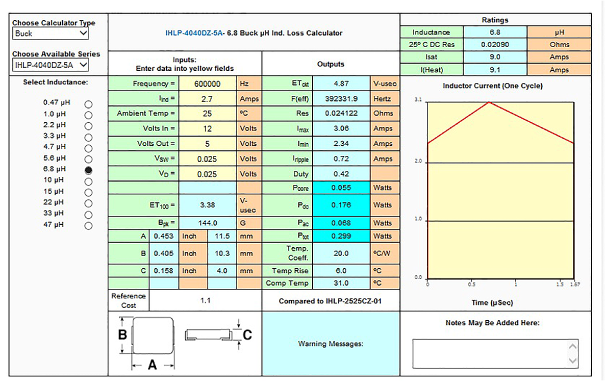
Figure 1. Vishay Inductor Calculation display results. Graphic supplied with permission from Vishay Intertechnology, Inc.
Capacitor Selection
We begin with a short discussion about the three types of ceramic capacitors, Class I, Class II, and Class III where Class I also includes the common CGO (NPO) type. The most common types are X5R, X7R, and Y5V. It is important to understand the difference among these types when specifying a ceramic capacitor for switching regulators. The change of capacitance over temperature is a very important characteristic and should be considered. Table 1 is assembled from data from ceramic capacitor supplier's websites. This table clearly shows the change in capacitance over temperature.
| Type | % ΔC | Temperature Range (°C) | Tolerance (%) |
| X5R | ±15 | -55 to +85 | K = ±10 |
| X7R | ±15 | -55 to +125 | K = ±10 |
| Y5V | +22/-82 | -30 to +85 | Z = -20/+80 |
| Z5U | ±22/-56 | -10 to +85 | M = ±20 |
| NPO | ±30ppm/°C | -55 to +125 | J = ±5 |
To further complicate matters, the actual capacitance value changes with the applied DC bias. Figure 2 is a plot from tutorial 55275 on choosing ceramic capacitors. It illustrates our point. I highly recommend that the reader take the time to consult this practical tutorial containing good application data and good common-sense design examples!
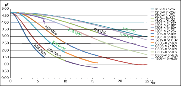
Figure 2. Temperature variation vs. DC voltage for select 4.7µF capacitors.
Practical Guide for Selecting the Input and Output Capacitors
Input Capacitor Selection
Why do I need an input capacitor? The input filter capacitor reduces peak currents drawn from the power source; it reduces noise and voltage ripple on the input caused by the circuit's switching. The input capacitor's RMS current requirement (IRMS) is defined by the following equation.
IRMS= IOUT(MAX) × SQRT [VOUT × (VIN - VOUT)/VIN]
where, IOUT(MAX) is the maximum load current. IRMS has a maximum value when the input voltage equals twice the output voltage. Without getting into a long derivation, we can use the basic equation for a capacitor, C = I DV/DT, and derive:
CIN= IOUT(MAX) × D × (1 - D)/n × FSW × ΔVIN
Where:
- D is the duty cycle ratio = VOUT/VIN
- n is the estimated converter efficiency
- FSW is the converter switching frequency
- ΔVIN represents the allowable input voltage ripple.
It should be noted that the input voltage ripple reaches the maximum value for a single phase converter at 50% duty cycle.
Output Capacitor Selection
The output capacitor of a switching regulator is a critical part of overall output performance. The inductor and the output capacitor form a lowpass filter. Additionally, the value of the output capacitor can greatly affect the converter's output transient response and the loop bandwidth.
The first step in determining the value of the output capacitor is to define the nature of the load. This also ties into the selection of the inductor as well. Basically, the change in the inductor's current is defined as di/dt = ΔV/L. So, for example, with a 12V input and 5V output using a 1µH inductor, the maximum rate of current change at 100% duty cycle would be 7A/µs as seen in Figure 3. What does this mean? Basically, if the load-step slew rate is greater than 7A/µs, then more output capacitance is needed to provide the necessary response to a transient load step. The other critical piece of information needed is the maximum allowable output-voltage change. Using the same example from above, we can take this a little further.
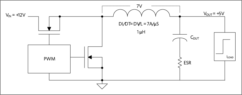
Figure 3. Diagram of inductor slew rate.
Calculate the maximum allowable output impedance, given the following requirements:
- VIN = 12V, VOUT = 5V
- Output current step 0.5A to 2.5A (ΔI = 2A)
- Maximum output voltage deviation = 50mV
- 20A/µs slew rate
Required capacitance impedance = 50mV/2A = 25mΩ. This means that the ESR of the output capacitor has to be 25mΩ or less.
Using the equations for COUT from the MAX17504 datasheet, we see that:
COUT = 0.5 ×I step × tresponse/ΔVOUT
Where, tresponse ≈ (0.33/FC + 1/fSW); FC is the targeted close-loop crossover frequency.
It is important to note that most regulator datasheets provide all the equations needed to help the designer calculate and select the input and output capacitors.
Part Selection and Simulation Design
Suppose that company X is designing a high-performance RF front-end that has a very wide operating frequency range. The input voltage varies from 20V to 35V and the circuit requires 3.3V at 2A and 5V at 2.5A. The RF signal chain has very sensitive low-noise circuits, and the designer wants to control the placement of the power-supply switching harmonics by applying an external clock to both regulators. In this way, the switching frequencies are identical and in phase with each other. Beat frequencies can be generated by converters not synchronized to the same clock. The beat frequencies and converter switching harmonics may fall within the operating range of the equipment and are very hard to eliminate.
Step 1: Search for the Regulator
Use the parametric search tool from the suppliers' website to narrow the regulator selection (Figure 4).
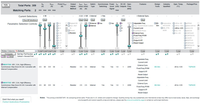
Figure 4. Start the regulator search with the supplier's parametric search tables. This is an example of the search on the Maxim Integrated website.
Use the following parameters:
- VINMAX to > 38V
- IOUT > 2.5A
- Synchronous switching = yes
Now switch the type box to Internal and then check the External Sync box. Two suitable parts are found. For this design the MAX17503 is chosen. Note that the MAX17504 could also be used at the expense of an inductor with a higher current saturation rating. Checking both data sheets, the peak-switch current limit of the MAX17504 is typically 5.1A versus 3.5A for the MAX17503. In general, the saturation rating of the inductor must be higher than the switch current limit. So for this example, the MAX17503 may allow for a physically smaller size inductor. The internal switch current limit is usually not found on parametric search tools, so one must inspect the data sheet to determine this value.
Step 2: Simulate the Design
After careful consideration based on application requirements, the appropriate converter is chosen. The next step is to choose the surrounding components such as the power inductors, input and output capacitor, and feedback resistors used to set the output voltage and component values for the compensation network. A convenient EE-Sim Design® tool (Figure 5)6 is a free power-supply design aid that gives both novice and experienced power-supply engineers a convenient way to design and optimize a regulator's transient response and loop stability.
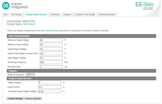
Figure 5. Enter the design requirement parameters.
Click the EE-Sim simulation tool and enter the application parameters. Then click the Create Design box which will provide the circuit diagram seen below (Figure 6) where the inductor, capacitor, and resistor values are automatically chosen. It is important to note that when choosing input/output capacitor values, take a close look at the VBIAS-versus-capacitance curve as the actual capacitance could decrease depending on the applied voltages. The capacitance values can be manually changed in EE-Sim to reflect the actual capacitance. This topic is covered extensively in the tutorial 5527.5
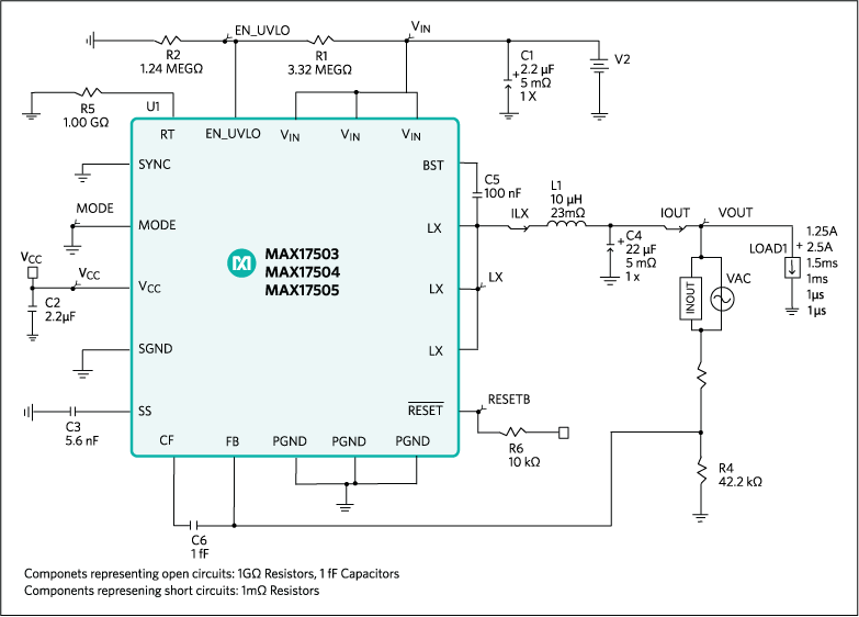
Figure 6. Solution schematic.
By clicking on the Analyze box, EE-Sim provides the option to do a steady-state, transient, or AC Analysis. A good start for the simulation would be to click the AC Analysis button and then the Run Analysis box (Figure 7) to check for stability. The rule of thumb is to have at least 45 degrees of phase margin at unity gain.
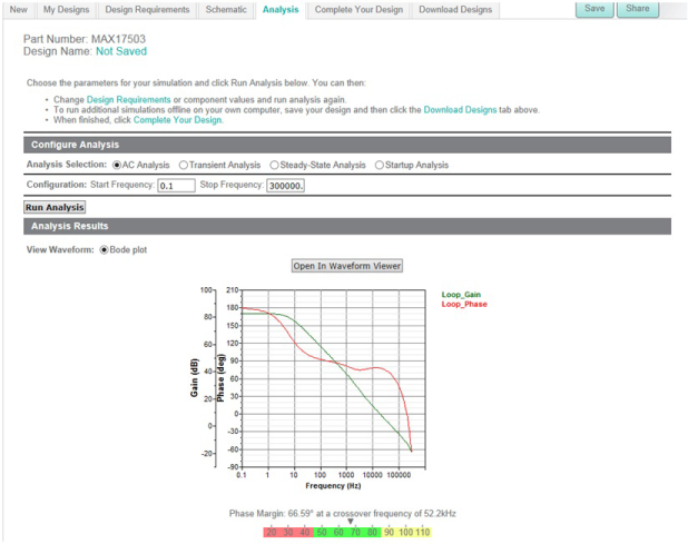
Figure 7. Configure the analysis type.
The bode plot below (Figure 8) shows that the phase margin at unity gain is 66.59 degrees at a crossover frequency of 52.2kHz.
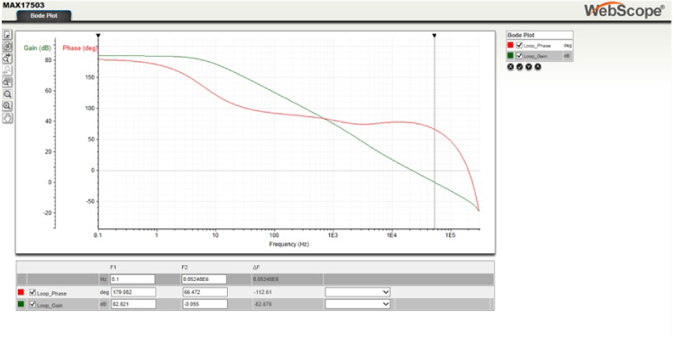
Figure 8. Bode plot for measuring loop stability.
Next we can look in the time domain to see how the output responds to a change in load current. Click on the Transient Analysis button. You can then select the voltage and current waveforms and use the Marquis Zoom to measure the output voltage deviation (Figure 9). In this example for a 1.25A load step, the output dips down to 4.85V, and when the load step is released, the voltage jumps to a peak of 5.135V.
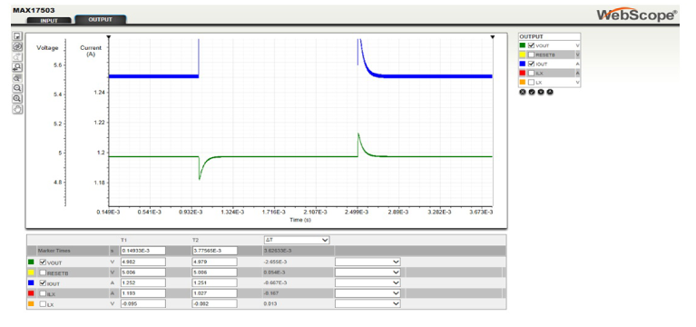
Figure 9. Transient response simulation.
It should be noted, finally, that there are many other waveforms available for view from the simulation. Simply select the various signals in the output box to the right.
Summary
Hopefully, this application note has provided a useful starting demonstration for engineers involved in selecting DC-DC regulators.
In Part 1 , of this three-part application note series, we began with a good foundation and basic understanding of voltage mode (VM) and current mode (CM) converters. Understanding the differences is important and will help the engineer make the right choice when there are so many options from many suppliers. Trade-offs in performance and cost are well explained between these two types of converters. In Part 2 ,topologies that improve efficiency over a wide range of output loads and explained various forms of pulse frequency modulation (PFM) helped engineers further. In portable equipment these topologies are widely used so a good understanding of their operation with trade-offs is key.
As power management is a vast topic, there have been thousands of papers written that examine various levels of detail. Additional advice on proper selection of inductors, input capacitors, and other components can be found in various application notes and product data sheets. The References below will prove useful for those wishing to expand their knowledge in power-supply design.
参考电路
[1] Eichhorn, Travis, "Estimate Inductor Losses Easily in Power Supply Designs," Power Electronics Technology (April 2005). https://www.powerelectronics.com/content/estimate-inductor-losses-easily-power-supply-designs.
[2] Vishay Inductor Loss Calculation Tool. http://www.vishay.com/inductors/calculator/calculator/.
[3] Coilcraft Inductor Value Tool. http://www.coilcraft.com/apps/selector/selector_1.cfm.
[4] Coilcraft Power Loss Tool. http://www.coilcraft.com/apps/loss/loss_1.cfm.
[5] Fortunato, Mark, Analog Devices tutorial 5527, "Temperature and Voltage Variation of Ceramic Capacitors, or Why Your 4.7µF Capacitor Becomes a 0.33µF Capacitor."
[7] Analog Devices User Guide 5861, "EE-Sim User Manual," March 2014.
A similar version of this application note appeared February 2015 on HOW2POWER.com.