

ADP5360
RECOMMENDED FOR NEW DESIGNSAdvanced Battery Management PMIC with Ultra Low Power Fuel Gauge, Battery Protection, Buck and Buck Boost
- Part Models
- 2
- 1ku List Price
- Starting From $2.78
Overview
-
Linear battery charger
- High accuracy and programmable charge terminal voltage and charge current up to 320 mA
- Compliant with JEITA charge temperature specification
- Li-Ion and Li-Poly battery monitor and protection
- Voltage-based fuel gauge with adaptive filter limitation
- Independent battery protection of overcharge and overdischarge
- Temperature sensor with external NTC
-
Ultralow quiescent current buck converter
- Quick output discharge option
- Ultralow quiescent current buck boost converter
- Quick output discharge option
- Supervisory with manual reset (MR) and watchdog timer
- Shipment mode extends battery life
- Full I2C programmability with dedicated interrupt pin
The ADP5360 combines one high performance linear charger for a single lithium-ion (Li-Ion)/lithium-polymer (Li-Poly) battery with a programmable, ultralow quiescent current fuel gauge and battery protection circuit, one ultralow quiescent buck, one buck boost switching regulator, and a supervisory circuit that can monitor output voltage.
The ADP5360 charger operates at up to 6.8 V to prevent USB bus spiking during disconnect or connect scenarios.
The ADP5360 features an internal isolation field effect transistor (FET) between the linear charger output and the battery node. The full battery protection features are activated when the device is in the battery overcharge and overdischarge fault conditions.
The ADP5360 fuel gauge uses a voltage-based algorithm with an adaptive filter limitation solution. The fuel gauge reports real-time battery state of charge (SOC) for the rechargeable Li-Ion battery with ultralow quiescent current.
The ADP5360 buck regulator operates at 1.0 MHz switching frequency in forced pulse-width modulation (FPWM) mode. In hysteresis mode, the regulator achieves excellent efficiency at a low output power.
The ADP5360 buck boost regulator only operates in hysteresis mode and outputs a voltage less than or greater than the battery voltage.
The ADP5360 supervisory circuits monitor the regulator output voltage and provide a power-on reset signal to the system. A watchdog timer and an external pushbutton can reset the microprocessor.
The I2C-compatible interface enables the programmability of all battery charging parameters, the protection threshold, the buck output voltage, and the status bit readback.
The ADP5360 operates over the −40°C to +85°C junction temperature range and is available in a 32-ball, 2.56 mm × 2.56 mm wafer level chip scale package (WLCSP).
Applications
- Rechargeable Li-Ion/Li-Poly battery-powered devices
- Portable consumer devices
- Portable medical devices
- Wearable devices
Documentation
Data Sheet 1
User Guide 2
ADI has always placed the highest emphasis on delivering products that meet the maximum levels of quality and reliability. We achieve this by incorporating quality and reliability checks in every scope of product and process design, and in the manufacturing process as well. "Zero defects" for shipped products is always our goal. View our quality and reliability program and certifications for more information.
| Part Model | Pin/Package Drawing | Documentation | CAD Symbols, Footprints, and 3D Models |
|---|---|---|---|
| ADP5360ACBZ-1-R7 | 32-Ball WLCSP (2.56mm x 2.56mm x 0.5mm) | ||
| ADP5360ACBZ-2-R7 | 32-Ball WLCSP (2.56mm x 2.56mm x 0.5mm) |
This is the most up-to-date revision of the Data Sheet.
Software Resources
Evaluation Software 1
Can't find the software or driver you need?
Evaluation Kits

Study Watch 4.5 User Guide
Resources
Software
Vital Signs Monitoring (VSM) Watch
Resources
Software


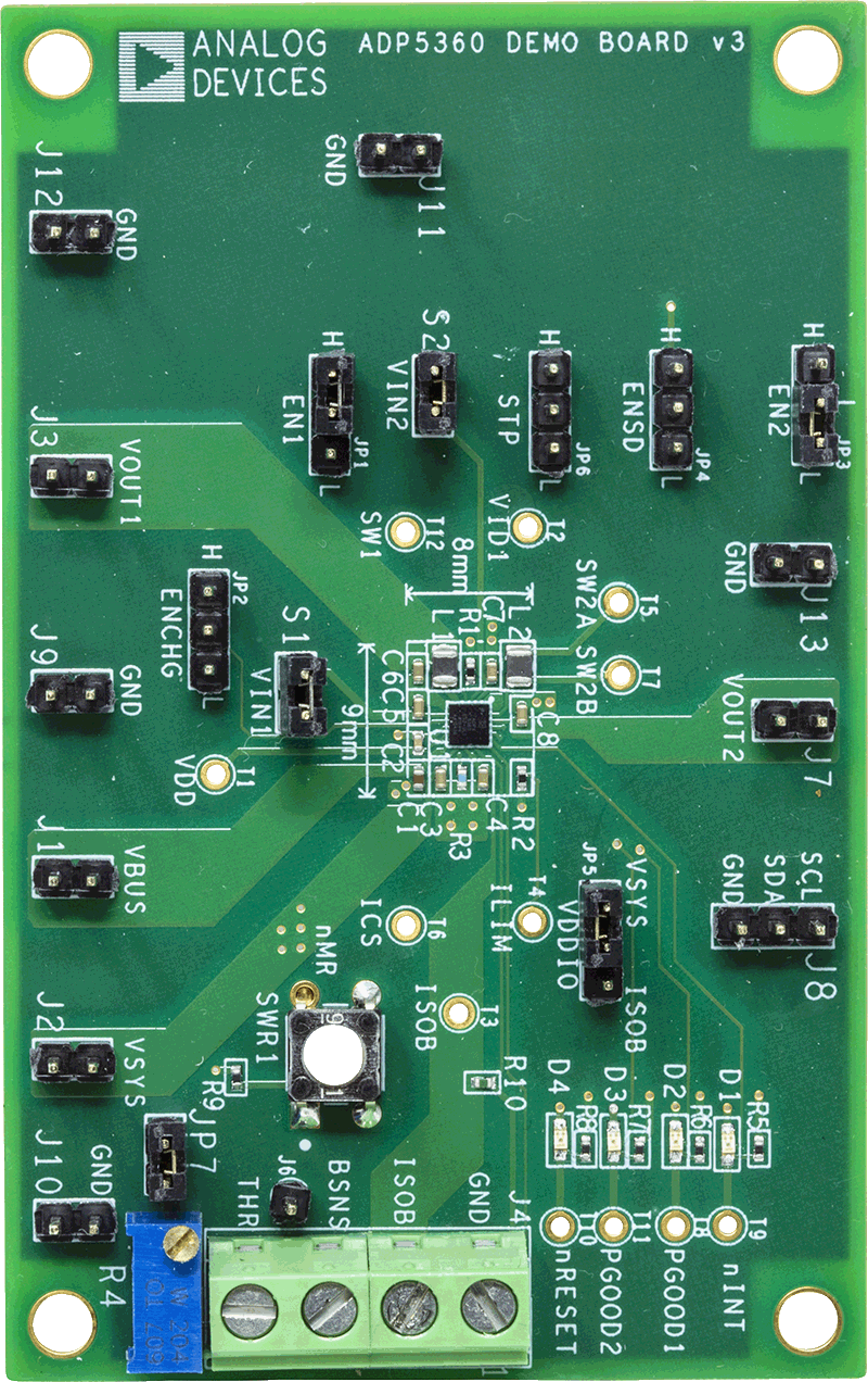
ADP5360 Evaluation Board