Power Supply for DDR-SDRAM Termination Operates From 3V to 5.5V Input
要約
Double data rate (DDR) synchronous dynamic random access memory (SDRAM) has gained popularity recently. The DDR memory needs active termination, VTT, that tracks the main memory voltage VDDQ. This application note provides a switching regulator solution to provide a ½ tracking output for VTT termination using MAX1957 pulse-width modulation (PWM) buck controller.
Double data rate (DDR) synchronous dynamic random access memory (SDRAM) has gained popularity because it can deliver double the data rate and reduced power consumption, compared to SDRAM at the same clock speed. These advantages come with more complex termination voltage requirements.
The DDR termination supply, VTT, must now be capable of sourcing as well as sinking current. VTT must track ½VDDQ, the output supply voltage (currently VDDQ is 2.5V, with ±3% accuracy). The input receiver is now a differential stage, requiring a reference bias, VTTR, which must track the termination voltage VTT to within ±40mV (refer to JDEC standards JDSD79 and JDSD8-9).
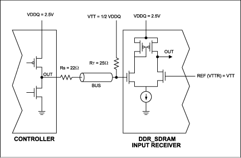
Figure 1 is a typical output buffer and input receiver stage with series stub termination logic for 2.5V (SSTL-2) in a DDR_SDRAM single terminated system. For double termination, used in the case of a long bus, two RTs terminate each end of the bus.

Figure 1. Single terminated SSTL-2 DDR_SDRAM system.
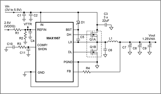
The MAX1957 circuit in Figure 2 provides VTT and VTTR for DDR_SDRAM. The MAX1957 has a reference input (REFIN) that connects to the non-inverting input of the internal error amplifier to regulate the output VTT to the same voltage as REFIN. To have VTT and VTTR track ½VDDQ, REFIN is developed by a resistor voltage divider (R1 and R2) from VDDQ. Capacitor C6 is a decoupling filter. The MAX1957 operates as constant frequency PWM, such that VTT can source and sink current as required by the DDR-SDRAM. Components used in Figure 2 provide over 3 Amperes of source and sink capability, which is the maximum requirement for a 128Mb memory system.

Figure 2. MAX1957 typical application circuit for VTT and VTTR.
| Component | Quantity | Description |
| C1 | 1 | Cap. 10µF/6.3V X5R Ceramic. Taiyo Yuden: JMK212BJ106MG |
| C2 | 1 | Cap. 4.7µF/6.3V X5R Ceramic. Taiyo Yuden:JMK212BJ475MG |
| C3 | 3 | Cap. 22µF/6.3V |
| C4, C5 | 2 | Cap. 0.1µF/50V X7R Ceramic. Taiyo Yuden UMK107BJ104KA |
| C6 | 1 | Cap. 1500pF/50V X7R Ceramic. Murata GRM89X7R152K50 |
| C7, C8, C9 | 3 | Cap. 270µF/2V SP Capacitor. Panasonic EEFUE0D271R |
| C10 | 1 | Cap. 470pF/50V X7R Ceramic. Murata: GRM89X7R471K50 |
| C11 | 1 | Cap. 68pF/50V X7R Ceramic. Murata: GRM39COG680J50 |
| D1 | 1 | Diode, Schottky, 30V, 100mA, SOT-23. Central: CMPSH-3 |
| IC | 1 | IC, Synch Buck controller: MAX1957 |
| L1 | 1 | Inductor, 2.7µH, 6.6A. Coilcraft: DO3316P-272HC |
| R1, R2 | 2 | Resistor, 0805, 1K, 1% |
| R3 | 1 | Resistor 51K, 0805, 5% |
| R4 | 1 | Resistor 10K, 0805, 5% |
| Q1/2 | 1 | Transistor, Dual MOSFET
Fairchild FDS6890A 20V, 0.018Ω |
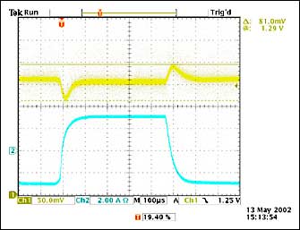
Figure 3 shows VTT and VTTR when subjected to a -3A to +3A step load at VTT. The peak voltage deviation of VTT is less than ±40mV.

Figure 3. Top trace: voltage VTT (AC coupled). Bottom trace: current ITT step from -3A to +3A and from +3A to -3A.
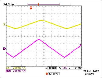
Figure 4 shows VDDQ, VTT tracks to half of VDDQ as VDDQ ramps up and down, showing the change in VTT is half of the change in VDDQ.

Figure 4. Top trace: voltage VTT (AC coupled). Bottom trace: 2.5V VDDQ (AC coupled).
It has been shown that the MAX1957 can be used as the controller for synchronous buck converter to provide termination voltage VTT for DDR_SDRAM systems. For applications requiring higher current, the drive circuit of the MAX1957 is capable of driving large external power MOSFETs for output current up to 20A.


