Maximize Cycle Life of Rechargeable Battery Packs with Multicell Monitor IC
Maximize Cycle Life of Rechargeable Battery Packs with Multicell Monitor IC
著者
Jon Munson
2010年04月01日
Rechargeable battery packs prematurely deteriorate in performance if any cells are allowed to overdischarge. As a pack becomes fully discharged, the ILOAD • RINTERNAL voltage drop of the weakest cell(s) can overtake the internal VCELL chemical potential and the cell terminal voltage becomes negative with respect to the normal voltage. In such a condition, irreversible chemical processes begin altering the internal material characteristics that originally provided the charge storage capability of the cell, so subsequent charge cycles of the cell do not retain the original energy content. Furthermore, once a cell is impaired, it is more likely to suffer reversals in subsequent usage, exacerbating the problem and rapidly shortening the useful cycle life of the pack.
With nickel-based chemistries, an over-discharge of a set of series-connected cells does not necessarily lead to a safety hazard, but it is not uncommon for one or more cells to suffer a reversal well before the user is aware of any significant degradation in performance. By then, it is too late to rehabilitate the pack. In the case of the more energetic lithium-based cell chemistries, reversals must be prevented as a safety measure against overheating or fire. Monitoring the individual cell voltages is therefore essential to ensure a long pack life (and safety with lithium cells).
Enter the LTC6801, developed to provide integrated solutions for these specific problems. The LTC6801 can detect individual cell overvoltage (OV) and undervoltage (UV) conditions of up to twelve series connected cells, with cascadable interconnections to handle extended chains of devices, all independent of any microprocessor support.
Features of the LTC6801
The operating modes and programmable threshold levels are set by pin-strap connections. Nine UV settings (from 0.77V to 2.88V) and nine OV settings (from 3.7V to 4.5V) are available. The number of monitored cells can be set from 4 to 12 and the sampling rate can be set to one of three different speeds to optimize the power consumption versus detection time. Three different hysteresis settings are also available to tailor behavior of the alarm recovery.
To support extended configurations of series-connected cells, fault signaling is transmitted by passing galvanically isolated differential clock signals in both directions in a chain of “stacked” devices, providing excellent immunity to load noise impressed on the battery pack. Any device in the chain detecting a fault stops its output clock signal, thus any fault indication in the entire chain propagates to the “bottom” device in the stack. The clock signal originates at the bottom of the stack by a dedicated IC, such as the LTC6906, or a host microprocessor if one is involved, and loops completely through the chain when conditions are normal.
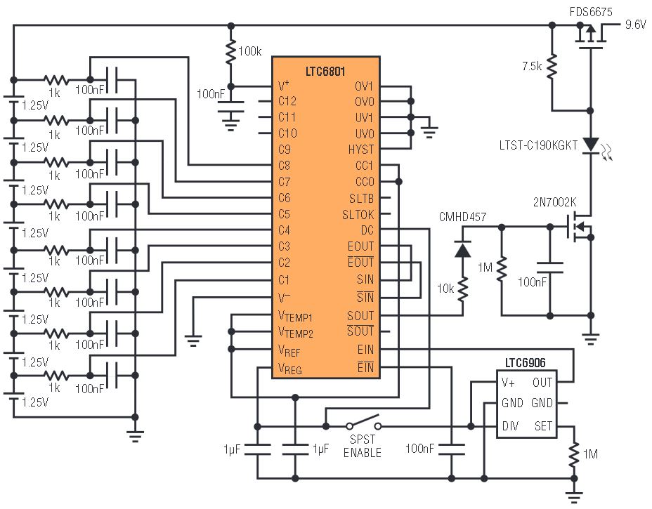
In many applications, the LTC6801 is used as a redundant monitor to a more sophisticated acquisition system such as the LTC6802 (for example, in hybrid automobiles), but it is also ideal as a standalone solution for lower-cost products like portable tools and backup power sources. Since the LTC6801 takes its operating power directly from the batteries that it monitors, the range of usable cells per device varies by chemistry in order to provide the needed voltage to run the part— from about 10V up to over 50V. This range supports groupings of 4–12 Li-ion cells or 8–12 nickel-based cells. Figure 1 shows how simply an 8-cell nickel pack can be monitored and protected from the abuse of overdischarge. Note that only an undervoltage alarm is relevant with the nickel chemistries, though a pack continuity fault would still be detected during charging by the presence of an OV condition.

Figure 1. Simple load-disconnect circuit to prevent excessive discharge of a nickel-cell pack.
Avoiding Cell Reversals
Cell reversal is a primary damage mechanism in traditional nickel-based multicell packs and can actually occur well before other noticeable charge-exhaustion symptoms set in.
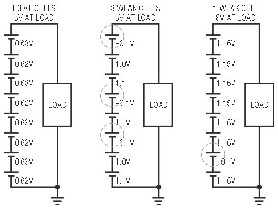
Consider the following scenario. An 8-cell nickel-cadmium (NiCd) pack is powering a hand tool such as a drill. The typical user runs the drill until it slows to perhaps 50% of its original speed, which means that the nominal 9.6V pack is loading down to about 5V. Assuming the cells are perfectly matched as in the left diagram of Figure 2, this means that each cell has run down to about 0.6V, which is acceptable for the cells. However, if there is a mismatch in the cells such that perhaps five of the cells are still above 1.0V, then the other three would be below zero volts and suffer a reverse stress as shown in the middle diagram of Figure 2.

Figure 2. Pack discharge conditions that promote cell reversals may not be apparent from load potential.
Even assuming that there is only one weak cell in the pack (a realistic scenario) as in the right diagram in Figure 2, the first cell reversal might well occur while the stack voltage is still 8V or more, with just a subtle reduction in perceived pack strength. Because of the inevitable mismatching that exists in practice, users unknowingly reverse cells on a regular basis, reducing the capacity and longevity of their battery packs, so a circuit that makes an early detection of individual cell exhaustion offers significant added value to the user.
Using the LTC6801 Solution
The lowest available UV setting of the LTC6801 (0.77V) is ideal for detecting depletion of a nickel-cell pack. Figure 1 shows a MOSFET switch used as a load disconnect, controlled by the output state of the LTC6801. Whenever a cell becomes exhausted and its potential falls below the threshold, the load is removed so that cell reversal and its degradation effects are avoided. It also allows the maximum safe extraction of energy from the pack since there are no assumptions made as to the relative matching of the cells as might be the case with an overly conservative single pack-potential threshold function.
A 10kHz clock is generated by the LTC6906 silicon oscillator and the LTC6801 output status signal is detected and used to control the load disconnect action. Since this example does not involve stacking of devices, the cascadable clock signals are simply looped-back rather than passed to another LTC6801. An LED provides a visual indication that power is available to the load. Once the switch opens, the voltage of the weak cell tends to recover somewhat and the LTC6801 reactivates the load switch (no hysteresis with 0.77V undervoltage setting). The cycling rate of this digital load-limiting action depends on the configuration of the DC pin; in the fastest response mode (DC = VREG), the duty cycle of the delivered load power drops and tapers off, with pulsing becoming noticeable and slower as the weakest cell safely reaches a complete discharge.
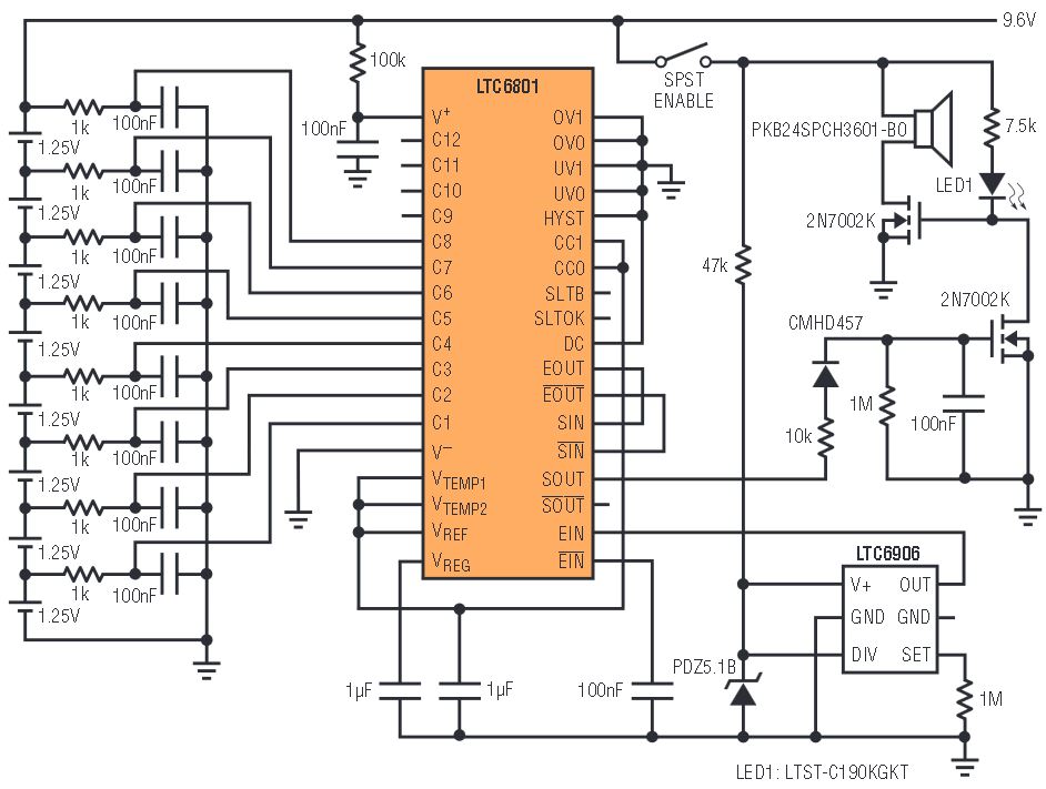
In some applications it is not acceptable to spontaneously interrupt the load when the weakest cell is nearing full discharge as depicted in Figure 1. For those situations, the circuit of Figure 3 might be a good alternative. This circuit does not force a load intervention, but simply provides an audible alarm indication that the battery is near depletion. Here the LED provides an indication that the alarm is active and that no cells are exhausted.

Figure 3. Alternative circuit provides an audible warning of the need to recharge the pack without interrupting service to the load.
An LTC6801 idle mode is invoked whenever the source clock is absent, and power consumption then drops to a miniscule 30μA, far less than the typical self-discharge of the pack. In both figures, the circuits show a switch that disables the oscillator (and other peripheral circuitry) in order to place the circuit into idle mode when not being used so that battery drain is minimized.
Conclusion
The LTC6801 simultaneously monitors up to 12 individual cells in a multicell battery pack, making it possible to maximize the pack’s capacity and longevity. It can also be cascaded to support larger battery stacks. The device has a high level of integration, configurability and well thought out features, including an idle mode to minimize drain on the pack during periods of inactivity. This makes the LTC6801 a compact solution for improving the performance and reliability of battery powered products.


