Implementing an ADC with a Microcontroller, an Op Amp, and Resistors
要約
This design idea explains how to implement an 8-bit analog-to-digital converter (ADC), using a microcontroller and some common components.
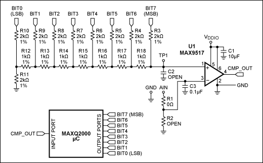
Analog-to-digital converters (ADCs) are used in a wide range of electronic devices. However, most of the low-cost microcontrollers do not include an ADC peripheral. This design idea provides a way to implement an 8-bit ADC using a microcontroller and some common components. The circuit consists of resistors and an operational amplifier (Figure 1).

Figure 1. ADC circuitry.
The R3–R18 resistors form an R/2R resistor ladder network, which converts the digital information into an analog output. In other words, it is a simple DAC. Bit7 (MSB) (the most significant bit) to Bit0 (LSB) (the least significant bit) are driven from the digital output ports of the microcontroller. The equation for the output voltage of the DAC is:

where VDDIO is the microcontroller's I/O supply voltage. The Bit[7:0] is the decimal equivalent of the binary DAC input.
The operational amplifier is used as a comparator that compares the output of the DAC and the analog input (AIN). The output of the comparator (CMP_OUT) connects to the input of the microcontroller.
The microcontroller output data varies cyclically in a descending order, and feeds into the DAC inputs. Each instantaneous DAC output is compared to the analog input voltage. The comparator output will toggle low when the DAC output is lower than the analog input. The comparator output is fed back to the microcontroller's input port. Upon receiving a logic-low signal from the comparator, the microcontroller stops and saves the DAC input data (microcontroller output data). This final DAC input data is the ADC output.
Listing 1 provides sample code written for Maxim's MAXQ2000 microcontroller.
#include "bitbanging_iomaxq200x.h"

void main(void)
{
  int wait;
  char DAC_out;

  PD0=0xFF;  //Sets IO port 0 to output (This port shows the ADC result)

  PD3=0xFF;  //Sets IO port 3 to output (This port connects to the DAC input)

  PD6_bit.bit2=0; //Sets IO port 6, pin 2, to input
		   //This pin connects to the output of the comparator

  while(1)
  {
    //Set DAC output to the MAX (DAC output = 3.3v) at the beginning
//Then decrease the DAC output 1 LSB at a time,
//until the output of the comparator toggles low
    for(DAC_out=0xFF; DAC_out>=0; DAC_out--)
    {
      PO3=DAC_out;  //Sets the value of the output port 3 to DAC_out

      //wait for the output of the comparator to settle
      for(wait=0; wait<500; wait++);

      //if the DAC output = 0V, and the output of the comparator is still 1
      if(PI6_bit.bit2==1 && DAC_out==0)
        PO0=0;  //Sets the ADC result = 0
      else if(PI6_bit.bit2==1)
        continue;
      else  //if the output of the comparator becomes 0
      {
        PO0=PO3;  //the ADC result = the value of the output port 3
        break;
      }
    }
  }
}
Similarly, you can implement an ADC with a different resolution using the same concept. However, when implementing a high-resolution ADC, higher-quality resistors with lower tolerance are required to reduce the DAC output error.