AN-1295: Mechanical Design Tips for ADIS16375, ADIS16480, ADIS16485, and ADIS16488
Package Features
Package features for the ADIS16375, ADIS16480, ADIS16485, and ADIS16488 include four 2.4 mm diameter mounting holes, aluminum housing, and a dual-row, 24-pin, 1 mm pitch electrical interface connector. Figure 1 illustrates the connector side of the package. In this view, the connector pins face up, and the four mounting holes and four screw heads are visible. The four machine screw heads are part of the internal package assembly and are not part of the system-level installation process. Figure 2 illustrates the lid side of the package. In this view, eight holes are visible, of which four are used in the system-level installation process.
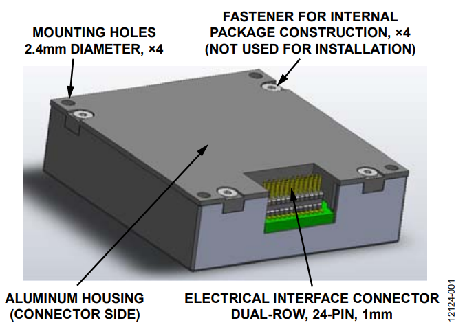
Figure 1. Connector-Up View.
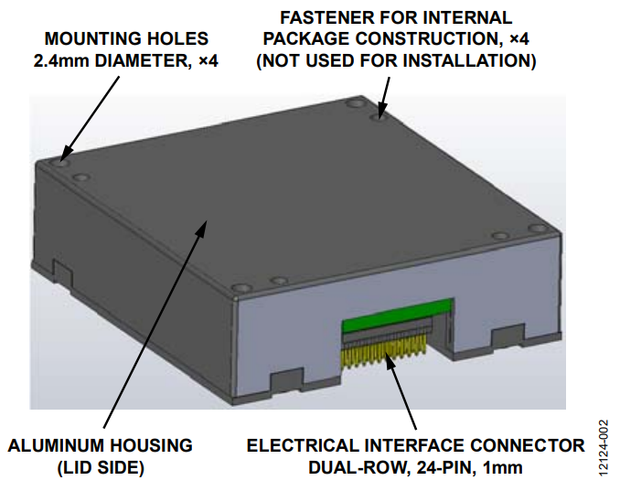
Figure 2. Connector-Down View.
Package Basics
Mechanical Sensitivity
The package for the ADIS16375, ADIS16480, ADIS16485, and ADIS16488 supports both connector-down and connector-up approaches. Connector-down means the mating connector is on the same plane as the mounting surface. Connector-up means the mating connector is not on the same plane as the mounting surface. Regardless of the connector orientation, follow these three guidelines for best performance.
- Apply mounting force only to the four corners.
- Avoid residual, translational stress on the connector.
- Use 40 inch-ounces of torque on the mounting screws.
Mounting Hole Locations
Use the basic dimension in the package drawing to select the mounting-hole locations. Figure 3 provides a simplified view of the package drawing, with the basic dimensions highlighted. The diameter of the mounting holes must allow the mounting screws to pass through. In order to accomplish this, consider the following error contributions:
- Diameter of the mounting hole in the inertial measurement unit (IMU) package (2.4 mm maximum)
- Tolerance in the location of the electrical connector, with respect to the center of the mounting holes on the IMU package (±0.3 mm maximum)
- Tolerance in the location of the electrical connector, with respect to the center of the mounting holes on the mating surface
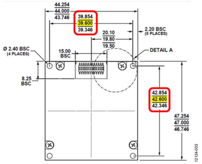
Figure 3. Outline Dimensions, Including Dimensions Between Mounting Holes.
While each system presents its own unique contributors for the third error term, the following calculation illustrates how to incorporate this contribution, assuming that it is also equal to ±0.3 mm:

Equation
Keep in mind that the key objective is to protect the connector from translational force after attachment, so be sure to evaluate all opportunities that may contribute to the locational error between mounting hole and mating connector location.
Mounting Examples
Mounting Example 1: COnnector-Down, Resting on Washers
Figure 4 and Figure 5 illustrate the first example, in which the mating connector is on the mounting surface, the system printed circuit board (PCB). The IMU rests on four washers, which set the IMU body off the PCB surface and focus all the mounting force on the package corners. In addition, this approach uses washers and nuts on the back side of the PCB. The washers between the IMU and the PCB surface must be thick enough to ensure that the body of the IMU does not contact the mounting surface at any point, except where it makes contact with the washers. While a washer thickness of 0.25 mm accounts for package flatness variation, this thickness does not accommodate flatness variation in the PCB surface, so the final value is likely to be larger than 0.25 mm.
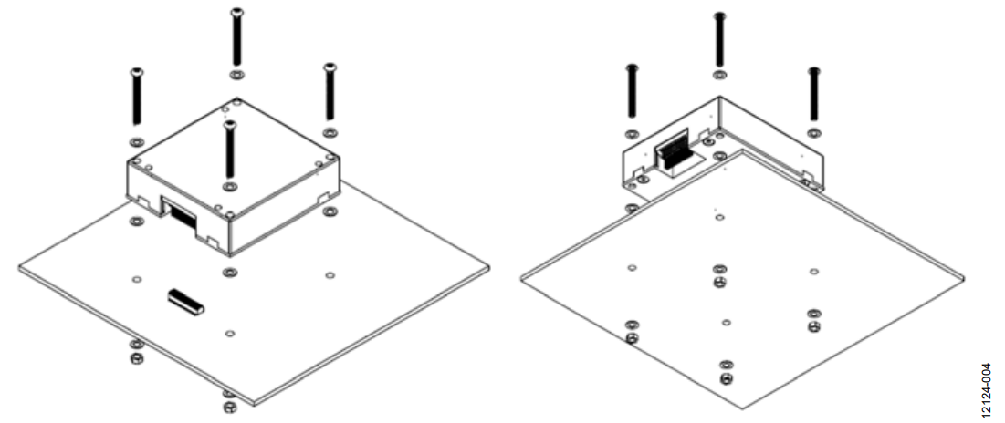
Figure 4. Mounting Example 1, Overview.
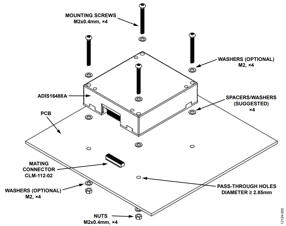
Figure 5. Mounting Example 1, Key Components and Attributes.
In addition to preventing contact between the package body and the PCB, ensure that the mating connector does not bottom out when mating with the electrical connector of the IMU, because this introduces the opportunity for an imbalance in the mounting forces. The CLM-11-02 series from SAMTEC offers enough clearance to avoid bottoming out. The MLE-112-02 series from SAMTEC offers greater mating coverage, but may require additional IMU elevation. Regardless of the mating connector solution, do not allow the connector bases to contact each other, as residual force is likely.
Due to a stack-up of independent mechanical tolerances, using threaded holes in the PCB for mounting the IMU may cause translational stress on the electrical connector. After installing the IMU to the PCB, ensure that any additional assembly activity avoids placing mechanical force on the connector of the IMU.
Mounting Example 2: Connector-Down, Resting on a PCB with a Cutout
Figure 6 and Figure 7 illustrate the second example, which uses a PCB with a cutout, which focuses the mounting force in the package corners without requiring washers to stand the package off the PCB surface. The shape of the cutout depends on a number of factors, including PCB thickness and the PCB fabrication design rules.
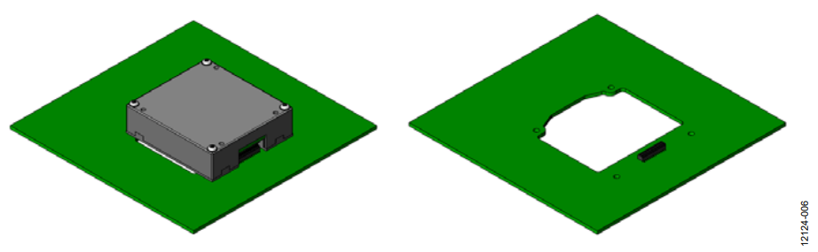
Figure 6. PCB with Cutout, With and Without Device.
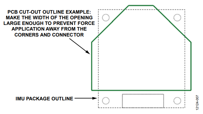
Figure 7. PCB Cutout Outline Example and IMU Package Outline.
Figure 7 provides a top-level view of an example PCB cutout area. The cutout geometry is flexible, and each situation requires specific attention. The key consideration is to focus the attachment force away from the center of the IMU body. The cutout in Figure 7 is actually wider than the IMU package, to support this objective.
Mounting Example 3: Connector-Up, Flex Cable Interface
Figure 8 shows a diagram for a third example, where the connector faces away from the mounting surface and the IMU rests on four washers, which set the IMU body off the mounting surface.
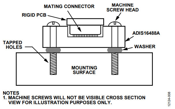
Figure 8. Mounting Example 3 Diagram.
The washers between the IMU and the PCB surface must be thick enough to ensure that the body of the IMU does not contact the mounting surface at any point, except where it makes contact with the washers. While a washer thickness of 0.25 mm accounts for package flatness variation, this thickness does not accommodate flatness variation in the PCB surface, so the final value is likely to be larger than 0.25 mm.
Mounting Example 4: Connector-Up, Flex Cable Interface with Hardware
Figure 9 shows a fourth example, where the connector also faces away from the mounting surface, but includes a rigid mating connector interface which leverages the mounting hardware to hold the connection in place. As is the case in the third example, the IMU rests on four washers, which set the IMU body off the mounting surface. With the exception of the rigid mount on the substrate of the mating connector, this example leverages all of the same attributes as the third mounting example.
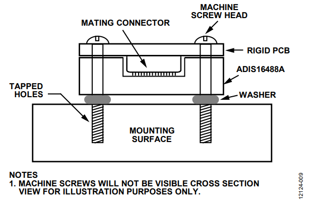
Figure 9. Mounting Example 4 Diagram.
Revision History
2/4—Revision 0: Initial Version
著者
