質問:
アナログ・カメラやIPカメラといった従来のビデオ伝送リンクと比べて、GMSLベースのソリューションには技術的に見てどのような優位性があるのでしょう? また、GMSLの潜在的な可能性については、どのようなことが言えますか?

回答:
旧来型のビデオ伝送ソリューションでは、CVBS(Composite Video Baseband Signal)のエンコーディングを使用するアナログ・カメラなどが使われてきました。その解像度は480iであり、制御信号をエンコードしたり、同軸ケーブルによって電力を伝送したりすることはできません。また、IP(Internet Protocol)カメラも、レイテンシが大きく、コストがかかるという欠点を抱えています。それだけでなく、システムを設計する際にはセキュリティの面で制約が生じます。それに対し、GMSLをベースとするビデオ伝送ソリューションであれば、最高12Gbpsの帯域幅でビデオ・データを伝送できます。しかも、同軸ケーブルにより、ビデオ信号に加えて制御信号や電力も伝送することが可能です。つまり、GMSLを採用すれば、ビデオ伝送性能を高めると同時に、BOM(Bill of Materials)コストを大幅に削減できます.
車載セキュリティ・システムの役割
バスやタクシー、トラックなどを含む多くの車両はセキュリティ・システムを搭載しています。そのインテリジェントなシステムは、監視、配車、緊急対応などを実現できるようにするために設計されています。具体的には、車内と周囲の環境をリアルタイムに監視する機能や、車両の位置を高い精度で特定する機能を備えています。また、ビデオ解析機能を利用することにより、異常な運転行動をタイムリーかつ正確に検出し、運転者に対して即座に警告を発せられるようになっています。あるいは、運転者と同乗者を潜在的な事故から守ることも可能です。更に、窃盗や交通事故などの事件が発生した場合には、捜査当局に対し、重要な映像を含むビデオ・データを法的な証拠として提出することもできます。
通常、車載セキュリティ・システムはビデオ・レコーダ、カメラ、モニタで構成されます。図1に典型的なシステムのブロック図を示しました。


図中のDVR(Digital Video Recorder)は、単なるレコーダではありません。そうではなく、データ処理を実行可能なサーバとしても機能します。DVRは、カメラ、I/O、車速パルスの送信システム、GNSS(Global Navigation Satellite System)などからの信号を受け取ります。また、録画したデータをローカルのハード・ディスクに保存する機能も担います。加えて、モニタとスピーカを利用してユーザとのやり取りを実現します。更に、LANポートまたは3G/4G/5Gを介してクラウドとの間で通信を実施します。通常、DVRは運転席の近くに設置されます。図2に示したのは、バスの車内に設置されたDVRの例です。


図2のシステムにおける主な構成要素としては、運転席の上に設置されたカメラが挙げられます。これは、運転手の行動を監視するためのものです。また、フロント・ドアや通路を監視するために、運転席のフロント・ドアにもカメラが設置されています。同様に、乗客の動きを監視し、運転手にドアを閉めるタイミングの目安を提示するためのカメラも使われています(図3)。通常、モニタやスクリーンは、運転手にとって見やすい運転席の近くに設置されます。そのモニタは、DVRまたは車両の安全システムとやり取りするための対話型インターフェースや、各カメラからのリアルタイムの映像を提供します。そうした機能により、運転手の意思決定を支援します。


図4に示したのもモニタの一例です。これは、乗客がバスの2階の座席の状況を確認できるようにするために使用します。


車両の安全システムは、基本的にCCTV(Closed-CircuitTelevision)として実現されます。このシステムは、運転手に対し、車内や死角の状況を確認するための映像を提供します。また、車両のリアルタイムの運行データや画像を、遠く離れた車両指令センター/配車センターに提供します。
ビデオ・レコーダ/カメラ/モニタから成る従来のソリューション
図5に示したのは、DVRを実現するための一般的なハードウェア・ソリューションの例です。主なシグナル・チェーンとしては、外部のアナログ・カメラから送信されるアナログ・ビデオ信号をビデオ用のA/Dコンバータ(ADC)に伝送する部分が挙げられます。このADCはビデオ・デコーダとも呼ばれます。その役割は、アナログ・ビデオ信号(CVBS信号)、アナログ高精細(AHD:Analog High Definition)信号、TVI(Transport Video Interface)信号をデジタル・ビデオ信号であるBT656に変換/デコードすることです。通常、CVBS信号を伝送する場合の最高解像度は576iとなります。また、TVIでは8K12.5pの信号を伝送できます。同様に、アナログ・オーディオ信号もI2Sの信号に変換されます。通常、図中のSoC(System on Chip)は、ユーザが使用するインターフェースにビデオ・ストリームを出力するためのビデオ出力ポートを備えています。そのポートは、一般的にはHDMI(High-Definition Multimedia Interface)®、VGA(Video Graphics Array)、CVBSに対応します。


図6に示したのは、アナログ・カメラをベースとする洗練されたシステムの構成例です。このシステムでは、ビデオ・プロセッサの高度な機能を活用することにより画質を向上させます。イメージ・センサーは光をキャプチャし、それをデジタル信号に変換します。その信号は、MIPI(Mobile Industry Processor Interface)、UART(Universal Asynchronous Receiver/Transmitter)/I2C、GPIO(General-Purpose Input/Output)などのインターフェースを使用してビデオ・プロセッサに送信されます。それを受け取るビデオ・プロセッサは極めて重要な役割を果たします。例えば、様々なディスプレイ規格との互換性を確保するための色空間変換、光学的な歪みを調整する画像補正、様々な照明の条件下で画像の鮮明度を最適化する露出補正といった高度な技術をサポートします。


後処理が実行されたら、その出力がTVI/AHD/CVBSエンコーダに引き渡されます。同エンコーダは、受け取った信号を従来のビデオ・インフラで伝送するのに適した標準的なビデオ・フォーマットにエンコードします。その後段では、75ΩのSMAコネクタを使用することで信号の完全性を維持します。
このシステムには電源回路も含まれています。同回路は、電源コネクタを介し、セットアップ全体に対して確実に電力を供給する役割を担います。また、制御と通信を更に強化するために、RS-232/TTL(Transistor-to-Transistor Logic)の低速信号に対応するコネクタも用意されています。そのため、接続オプションを容易に追加できます。
図7に、IPカメラを使用するシステムのアーキテクチャを示しました。このシステムでは、センサーで取得した未処理のデータを、カメラ・コントローラによって処理/解析できるようにするためにデジタル画像に変換します。図7に示したとおり、システムの最上流に位置するのは周辺環境の画像データをキャプチャするセンサーです。その後段に配置されるデータの経路は、複雑かつ精巧に最適化されています。


最初の処理を担うのは、MIPI-PHYです。ここでは、センサーの出力に対する最初のデジタル変換が行われます。このインターフェースにより、画像に対応するMIPIのパケットはピクセル・レベルにデコードされます。その結果となるデータは、カメラ・コントローラによって解析/調整されます。
同コントローラは、データの流れを調整し、後続の処理に備えるための重要なコンポーネントです。その後段に配置されているのはMAC(Media AccessControl)とイーサネットPHYです。これらはネットワーク通信を管理するために使用されます。具体的には、データのパケットのフォーマッティング、アドレスの指定、ネットワーク経由の送信の処理を担います。それにより、ネットワークに接続されたシステムとカメラのシームレスなインターフェースが確立されます。
図中のもう1つのイーサネットPHYは、SoCによって最終的な処理を行うためのデータを準備します。SoCは、受け取ったすべての情報を統合し、複雑な計算を実行し、統合されたビデオ・データに基づいて判断を下します。IPカメラを使用するシステムは、単に画像をキャプチャするのではありません。上記のような高度なフローにより、セキュリティ、監視、解析のアプリケーションで即座に使用できるようにデータを処理します。つまり、このシステムは、リアルタイム対応の環境で効率的かつ効果的にデータを処理できるだけの非常に高い能力を備えています。
アナログ・カメラを使用する場合、アナログ・ビデオ信号を伝送するために75Ωの同軸ケーブルが必要になります。また、電力を伝送したり、RS-232/RS-485によって追加の制御信号を伝送したりするためには、別途ケーブルを用意しなければなりません(図8)。


IPカメラを使用する場合、CAT3やCAT5といった標準的なイーサネット・ケーブルを使うことになります。PoE(Power over Ethernet)がサポートされていない場合には、電源ケーブルを追加しなければなりません。イーサネット・ケーブルは4組のツイスト・ペアから成ります(図9)。撚り線を使用することから、信号の干渉が緩和されます。

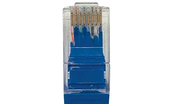
図10に、モニタ・システムのブロック図を示しました。この図は、ビデオ信号を効率的に管理/表示するように設計された高度なフレームワークを正確に描いたものです。その中心にあるのはコントローラであり、様々な入出力に対する調整を実施することでシームレスな動作を実現します。


このシステムの左端には、75Ωのコネクタが配置されています。それを介してアナログ・ビデオ入力がシステムに接続されます。そのビデオ信号はTVI/AHD/CVBSデコーダに引き渡されます。同デコーダは、多様なビデオ・フォーマットのデータを、標準化されたデジタル出力に変換します。それにより、後続の処理が容易になります。
TVI/AHD/CVBSデコーダには、I2Cのインターフェースを介してコントローラが接続されています。コントローラは、上述したデジタル・データを処理します。また、複数の重要な経路の連結点としても機能します。液晶ディスプレイ(LCD)とタッチ操作用のICは、コントローラと直接通信を行います。輝度などの映像の特性は、コントローラが制御を担うPWM(Pulse Width Modulation)調光によって決まります。また、コントローラはタッチ・パネルからの情報を入力として処理する役割も担います。タッチ・パネルを提供すれば、ユーザにとって操作性が向上することになります。
それ以外の通信インターフェースとしては、RS-422/TTLやGPIOなどが使われます。それぞれ、堅牢性の高い長距離のデータ伝送と一般的な入出力のタスクに使用されます。これらの機能は、ディスプレイの設定の制御や追加の機能の組み込みといった対話型のタスクの実現に不可欠です。
ケーブルについては、ドット単位のビデオ信号やアナログ・ビデオ信号の伝送に対応できるものが必要です。それだけでなく、モニタを接続するためにはRS-422の信号を伝送可能なケーブルも必要になります(図11)。


従来のハードウェア・ソリューションは、CCTVとして実現されていました。その種のシステムには、ビデオ・コーデック用のケーブル、同軸ケーブルまたはイーサネット・ケーブル、電源ケーブル、制御信号用のケーブル(RS-422/RS-485/RS-232)など、複数のケーブルが必要になります。そのため、設置作業が複雑になると共に、コストがかさむ可能性があります。
車載セキュリティ・システムで活きるGMSLの機能
カメラとディスプレイの数はますます増加しています。画質も向上する一方なので、ビデオ伝送にはより高いデータ・レートが求められます。アナログ・デバイセズが開発したGMSLは、このトレンドに対応したものであり、ビデオ伝送システムのアーキテクチャを簡素化することに大きく貢献します。GMSLを採用すれば、カメラからコンピュータへ、コンピュータからコンピュータへ、コンピュータからディスプレイへとビデオ・データを伝送できます。また、GMSLは数世代にわたって進化を続けています。その結果、より性能の高いコンピュータやソフトウェア定義型のアプリケーションに適した高度な機能/性能が提供されるようになりました。
なお、世代間の移行は、新世代のGMSLに前世代のGMSLに対する後方互換性を持たせることで容易に実現できるようになっています。
例えば、ADAS(Advanced Driver Assistance System:先進運転支援システム)では様々なセンサーが使用されます。GMSLを採用すれば、センサーに関連して必要になるすべての信号(MIPI-CSI、I2C、GPIOなど)を1本の同軸ケーブルまたはSTP(Shielded Twisted Pair)ケーブルで伝送できます。通常、GMSLによって接続されるカメラ(以下、GMSLカメラ)は、信号の伝送用に1つのコネクタしか必要としません。そのコネクタにより、ビデオ信号、電力、制御信号、同期信号、触覚信号、タッチ信号、ソフトウェアの更新データ、ステータス・レポートなどを伝送することが可能です(図12)。そのため、重量、消費電力、A/Vコスト、複雑さを大幅に低減できます。


アナログ・デバイセズのソリューションは、性能の面でSERDESの市場を牽引しています。現在は、データ・レートが最高12Gbpsの製品を量産しており、最適化された100種以上の製品を提供しています。GMSLを採用すれば、システムの小型化と消費電力の削減を図れることが保証されます。
カメラとディスプレイを使用するアプリケーションの市場は広がり続けています。それに対応するために、アナログ・デバイセズはGMSL製品のポートフォリオを拡充しました。表1は、アナログ・デバイセズが提供するGMSL2/GMSL3対応のシリアライザについてまとめたものです。この表には、各製品の主要なパラメータと機能を示してあります。一方、表2はGMSL2/GMSL3に対応するデシリアライザについてまとめたものです。サポートしているビデオ・インターフェースは、LVDS(Low Voltage Differential Signaling)、HDMI、MIPI CSI-2です。なお、表には示していませんが、GMSL1に対する後方互換性を備える製品として、GMSL2に対応するシリアライザ「MAX9295D」も提供しています。
| 品番 | MAX96717 | MAX96793 | MAX96751 |
| 製品ファミリ | GMSL2 | GMSL3 | GMSL2 |
| 対応するデバイス | カメラ | カメラ | ディスプレイ |
| 順方向の最高リンク・レート | 6Gbps(バージョンF/Rは3Gbps) | 12 Gbps | 6 Gbps |
| GMSLのリンク数 | 1 | 1 | 2 |
| ビデオ・インターフェース | CSI-2 DPHY:2.5Gbps/レーン | CSI-2 DPHY:2.5Gbps/レーン、 CSI-2 CPHY:3.42Gbps/レーン |
HDMI 1.4/2.0、 1ポート×4レーン、 HDMIオーディオに対応 |
| ビデオ・ポートの構成(DPHY) | 1ポート×4レーン | 1ポート×4レーン | – |
| ビデオ・ポートの構成(CPHY) | – | 1ポート×2レーン | – |
| パッケージのサイズ | 5mm×5mm、32ピン | 5mm×5mm、32ピン | 8mm×8mm、56ピン |
| バックチャンネル | I2C/UART/SPI | I2C/UART/SPI | I2C/UART/SPI/I2S |
| ASILのレベル | ASIL-B | ASIL-B | ASIL-B |
| ウォーターマーク | あり | ||
| 温度グレード | -40°C~105°C | -40°C~105°C | -40°C~105°C |
| 品番 | MAX96716A | MAX96724 | MAX96792A | MAX96752 |
| 製品ファミリ | GMSL2 | GMSL2 | GMSL3 | GMSL2 |
| 対応するデバイス | カメラ | カメラ | カメラ | ディスプレイ |
| GMSLのリンク数 | 2 | 4 | 2 | 2 |
| 順方向の最高リンク・レート | 6 Gbps | 6 Gbps | 12 Gbps | 6 Gbps |
| ビデオ・インターフェース | DPHY:2.5Gbps/レーン、 CPHY:4.56Gbps/レーン |
DPHY:2.5Gbps/レーン、 CPHY:5.7Gbps/レーン |
DPHY:2.5Gbps/レーン、 CPHY:5.7Gbps/レーン |
OLDI 1ポート×4レーン、 2ポート×4レーン、 1ポート×8レーン |
| ビデオ・ポートの構成(DPHY) | 2ポート×4レーン | 2ポート×4レーン、 4ポート×2レーン、 1ポート×4レーン+2ポート×2レーン |
2ポート×4レーン | – |
| ビデオ・ポートの構成(CPHY) | 2ポート×2レーン | 2ポート×4レーン、4ポート×2レーン、1ポート×4レーン+2ポート×2レーン | 2ポート×2レーン | – |
| パッケージのサイズ | 7mm×7mm、48ピン | 8mm×8mm、56ピン | 7mm×7mm、48ピン | 8mm×8mm、56ピン |
| バックチャンネル | I2C/UART/SPI | I2C/UART | I2C/UART/SPI | I2C/UART/SPI/I2S |
| ASILのレベル | ASIL-B | ASIL-B | ASIL-B | ASIL-B |
| 温度グレード | -40°C~105°C | -40°C~105°C | -40°C~105°C | -40°C~105°C |
GMSLがもたらすメリット、可能性
表1、表2には順方向の最高リンク・レートという項目があります。これは、シリアル・リンク上でGMSLのプロトコルによってエンコードされるビット・レートのことを指しています。同時に、I2C/UART/GPIOなどの制御信号も伝送されます。表3は、GMSLをベースとするソリューションと競合するアナログ・カメラ、IPカメラのソリューションを比較したものです。
| ソリューション | アナログ・カメラ | IPカメラ | GMSLカメラ |
| コーディング方式 | CVBS/TVI | H.264/H.265 | GMSL |
| 最高解像度 | CVBS: 576i (PAL) TVI: 8 M, 12.5 P |
4k、最高8k | GMSL3: 8MP、60P GMSL2: 8MP、30P |
| ビデオのレイテンシ | CVBS:約60ミリ秒 TVI:約100ミリ秒 |
200ミリ秒~500ミリ秒 | マイクロ秒のオーダー、非常に小さく確定的 |
| ケーブルによる制御データの伝送 | CVBS:不可 TVI:可、I2Cのみ |
可 | 可、I2C/UART/SPI/GPIO |
| ケーブルによる電力伝送 | 非対応 | PoE、複雑、能動部品が必要 | PoC、簡素、受動回路だけでよい |
| ハードウェアの複雑さ | カメラの設計が複雑 | カメラの設計が複雑 | カメラの設計が簡素 |
また、図13にはGMSLとカメラ(イメージ・センサー)を組み合わせたシステムのブロック図を示しました。


前掲の図6、図7と比較すると、GMSLに対応するSERDESソリューションを採用した場合、カメラ・モジュールに必要な部品点数を大幅に削減できることがわかります。また、GMSLであればI2C/UART/SPI/GPIOの信号を同時に双方向に伝送することが可能です。それにより、SoCはGMSLを介して遠く離れたイメージ・センサーのペリフェラルにアクセスすることができます。ペリフェラルの例としては、慣性計測ユニット(IMU:Inertial Measurement Unit)、Gセンサー、LEDコントローラ、パン/チルト/ズーム(PTZ)の制御システムなどが挙げられます。GMSLのレイテンシはマイクロ秒のオーダーなので、ユーザはGPIOを介して1フレームをトリガすることができます。GMSLカメラの外部インターフェースは、1本の同軸ケーブル(50Ω)またはSTPケーブルしか必要としません。
表1で取り上げたMAX96717/MAX96793シリーズの製品は、リファレンス・オーバー・リバース(RoR)クロッキングをサポートしています(図14)。これは、デシリアライザから逆方向のチャンネルを介して送信されるクロックを利用するというものです。それにより、センサー用のボードでは水晶発振器を使用する必要がなくなります。水晶発振器の数を減らすことにより、システム・コストの削減、信頼性の向上、基板レイアウトの簡素化といったメリットが得られます。


図15に示したのは、GMSLを利用するディスプレイのハードウェア・システムです。図13、図15からわかるように、GMSL対応のSERDESを使用するビデオ・インターフェースと制御用インターフェースは、イメージ・センサーと液晶ディスプレイ・パネルに直接接続されます。それにより、マイクロコントローラ、ビデオ・コーデック、RS-485/RS-232対応のドライバ/レシーバー、いくつかのコネクタが不要になります。GMSLに対応するSERDESソリューションにより、広いビデオ帯域幅、非常に小さく確定的なレイテンシ、極めてシンプルなハードウェア設計、1本の同軸ケーブル/STPケーブルのみによる低コストの外部インターフェースが実現されます。


まとめ
GMSLに対応するSERDESソリューションは、既存の車載DVRソリューションに代わる強力な選択肢となります。GMSLを利用すれば、帯域幅が広くレイテンシの小さいビデオ伝送を実現しつつ、各種の部材やケーブルにかかるコストを削減することができます。
参考資料
1 「アナログ・ビデオ信号について理解する」Analog Devices、2002年9月
2 Ferenc Barany「AN-945: System Bandwidth vs. Resolution for Analog Video(AN-945:アナログ・ビデオにおけるシステムの帯域幅と解像度の関係)」Analog Devices、2007年11月
3 Kainan Wang「GMSLカメラでGigE Visionカメラを置き換えることは可能なのか?」Analog Dialogue、Vol. 57、2023年12月