Using Safety Application Notes to Aid Safety Designs—Part 2: Plugging in the FMEDA

Using Safety Application Notes to Aid Safety Designs—Part 2: Plugging in the FMEDA
Jul 14 2026
Read other articles in this series.
Key Takeaways
|
Abstract
After doing some sanity checks to confirm whether the assumptions in deriving the component’s functional safety (FS) failure rate, failure mode distribution (FMD), and pin failure modes and effects analysis (FMEA), the next step system integrators need to take is to plug the data into their system’s failure modes, effects, and diagnostics analysis (FMEDA). With the availability of different methods to calculate the failure rate, die FMD, and pin FMEA information in Analog Devices, Inc.’s (ADI’s) safety application notes, there are several approaches to use such information, depending on the system integrator’s experience with safety-related system (SRS) designs or in doing technical safety analysis through FMEDA. This second part of the series aims to provide one of the approaches to the derivation of an FS-enabled part’s failure rate distribution considering the die FMD and pin FMEA.
Introduction
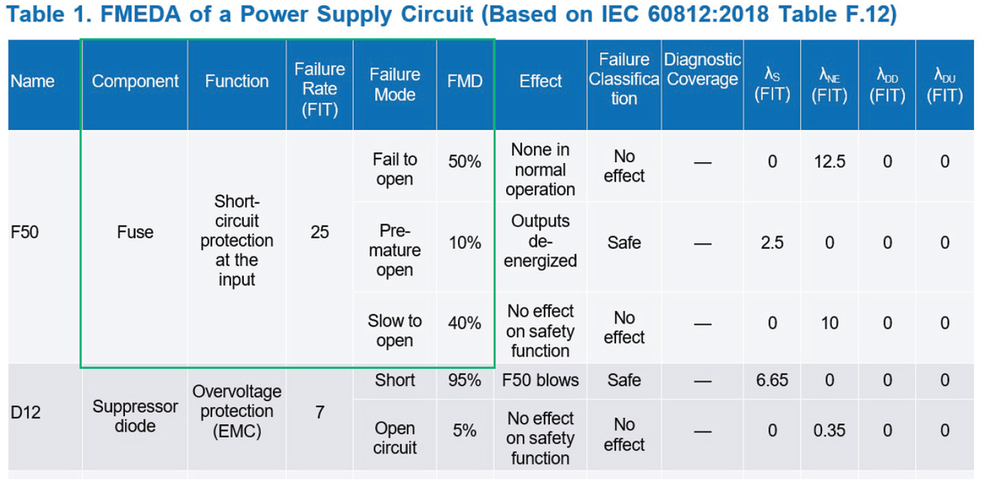
Part 2 of the Know Your Safety Application Notes series provides an example of a power supply circuit failure modes, effects, and diagnostics analysis (FMEDA) showing a component FMEDAs (as shown in Figure 1). Analog Devices, Inc.’s (ADI’s) safety application notes contain safety information that can be copied to the highlighted section of the FMEDA in Figure 1. This second part of the series aims to show how to utilize the information in a component’s safety application note and use it in a system-level FMEDA.1-3
Selecting the Reliability Prediction Method
After doing sanity checks of the assumptions used for the safety information found in a functional safety (FS)-enabled part’s safety application note, the next thing a system integrator needs to do is to select the appropriate reliability prediction method for their application as shown in Figure 2. This needs to be consistent with a technical safety analysis approach—for example, the use of one consistent source of reliability prediction.
| Component | Function | Failure Rate (FIT) | Failure Mode | FMD |
| Low-dropout (LDO) regulator | Provides low noise, regulated voltage output of 3.3V ±1.5% within 1.2ms after enabling | 7.15 | ||
| 0.39 |
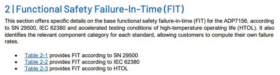
ADI’s safety application notes provide three types of reliability prediction methods: SN 29500, IEC 62380, or based on measurement in the lab, high-temperature operating life (HTOL). Part 1 of the Know Your Safety Application Note series discusses the differences between each method. Notably, HTOL and SN 29500 methods provide a failure rate for the whole integrated circuit (IC), while IEC 62380 gives a separate failure rate for die and package.1,4
If HTOL or SN 29500 are selected, the overall failure rate can also be further distributed into die and package failure rates using expert judgment. The SN 29500 base failure rate, an example specified in the automotive safety standard ISO 26262:2018—11 Section 4.6.2.1.2.4, can be distributed into die and package failure rates using the same ratio determined by the IEC 62380 method.5
With the highlighted information from Figure 1 applied to the ADP7156, Table 1 shows the completed failure rate column using the die failure rate (7.15 FIT) and package (0.39 FIT) based on IEC 62380.
Completing the Die FMD Column
The FMD shown in the safety application note refers to the die FMD as it is derived from the component die area ratio and complexity and from engineering expertise. Therefore, it can already be plugged into the failure mode and FMD section of the system-level FMEDA of that component. This is shown in Table 2. Without the safety application note, system integrators might have to allocate the failure rate equally across the failure modes from IEC 61508-2:2010 Table A.1. With the safety application note, they get a failure mode distribution based on the analysis of the actual IC.
| Component | Function | Failure Rate (FIT) | Failure Mode | FMD |
| LDO regulator | Provides low noise, regulated voltage output of 3.3V ±1.5% within 1.2ms after enabling | 7.15 | VOUT is off or stuck low close to 0V | 29% |
| VOUT regulates higher than target | 12% | |||
| VOUT regulates lower than target | 9% | |||
| VOUT output is oscillating but within regulation | 6% | |||
| VOUT is stuck close to VIN | 24% | |||
| VOUT settling time > 1.2ms | 3% | |||
| VOUT output is oscillating but outside regulation | 1% | |||
| No effect on system function | 16% | |||
| 0.39 |
Table 1 needs to have the 0.39 FIT associated with the pin failure modes distributed.
Generating the Pin FMD
Using the pin failure modes and effects analysis (FMEA), the pin FMD can be derived from the provided pin FMEA tables in the safety application note. Generally, the failure modes found in the die FMD will be similar to the pin FMD since such failure modes relate to the system function of the IC. Otherwise, it will just have some omissions, like in Table 3 where some FMD are tagged as 0%. Summing up the system-level failure modes, found in the pin FMEA tables’ effect column, to 100%, a pin FMD such as in Table 3 can be acquired.
After completing the FMEDA shown in Table 3, system integrators will need to define the effect of each IC failure mode for their specific safety function, identify the failure classification (safe, dangerous, no effect, no part) of each failure mode, and check whether the achieved dangerous undetected failure rate is sufficiently low given their target SIL.
| Component | Function | Failure Rate (FIT) | Failure Mode | FMD |
| LDO regulator | Provides low noise, regulated voltage output of 3.3V ±1.5% within 1.2ms after enabling | 7.15 | VOUT is off or stuck low close to 0V | 29% |
| VOUT regulates higher than target | 12% | |||
| VOUT regulates lower than target | 9% | |||
| VOUT output is oscillating but within regulation | 6% | |||
| VOUT is stuck close to VIN | 24% | |||
| VOUT settling time > 1.2ms | 3% | |||
| VOUT output is oscillating but outside regulation | 1% | |||
| No effect on system function | 16% | |||
| 0.39 | VOUT is off or stuck low close to 0V | 32.2% | ||
| VOUT regulates higher than target | 6.8% | |||
| VOUT regulates lower than target | 6.8% | |||
| VOUT output is oscillating but within regulation | 3.4% | |||
| VOUT is stuck close to VIN | 20.5% | |||
| VOUT settling time > 1.2ms | 0% | |||
| VOUT output is oscillating but outside regulation | 0% | |||
| No effect on system function | 30.3% |
Conclusion
In summary, utilizing ADI safety application notes streamlines technical safety analysis by providing the critical data needed to populate a component-level FMEDA. By selecting a consistent reliability prediction method—such as IEC 62380, SN 29500, or HTOL—and mapping the provided die FMD and pin FMEA directly into the analysis, system integrators can accurately distribute failure rates across various functional failure modes. This systematic approach transitions the workflow from an initial sanity check to a fully populated input section of the FMEDA, serving as the essential foundation for the final stages of safety analysis: classifying failures, determining safe and dangerous failure rates, and ultimately verifying the system’s overall SIL compliance.
References
1Bryan Borres. “Know Your Safety Application Notes—Part 1: Failure Rates.“ Analog Devices, Inc., August 2015.
2Bryan Borres. “Know Your Safety Application Notes—Part 2: Failure Mode Distribution.“ Analog Devices, Inc., October 2025.
3Bryan Borres. “Know Your Safety Application Notes—Part 3: Pin FMEA.“ Analog Devices, Inc., November 2025.
4Tom Meany. “Reliability Predictions for Integrated Circuits.” Analog Devices, Inc., December 2021.
5ISO 26262 Part 11, Road Vehicles—Functional Safety: Guidelines on Application of ISO 26262 to Semiconductors.” International Organization for Standardization, 2018.
About the Authors
Bryan Angelo Borres is a TÜV-certified functional safety engineer who focuses on industrial functional safety. As a senior functional safety engineer, he helps component designers and system integrators design functionally
Related to this Article
Products
PRODUCTION
Programmable Hex Voltage Supervisor with EEPROM
RECOMMENDED FOR NEW DESIGNS
0.3% Accuracy Dual-Channel Supervisory Circuit
PRODUCTION
High-Voltage, Overvoltage/Undervoltage, Protection Switch Controller
100VIN Micropower Isolated Flyback Converter with 150V/260mA Switch
High-Accuracy, Adjustable Power Limiter
1.2 A, Ultralow Noise, High PSRR, Fixed Output, RF Linear Regulator
Load-Dump/Reverse-Voltage Protection Circuits
Load-Dump/Reverse-Voltage Protection Circuits
Ultra-Small, Overvoltage Protection/Detection Circuits
125nA nanoPower Supervisory Circuits with Capacitor-Adjustable Reset and Watchdog Timeouts
Low-Power, Single/Dual-Voltage Window Detectors
Low-Power, Single/Dual-Voltage Window Detectors
High-Voltage, Low-Current Voltage Monitors in SOT Packages
Low-Power, Single/Dual-Voltage Window Detectors
Low-Voltage, Precision, Single/Dual/Triple/Quad-Voltage μP Supervisors