Abstract
The first part of this series discussed component failure rates and reliability prediction methods. Part 2 covers failure modes, effects, and diagnostics analysis (FMEDA), which is one of the available safety analysis tools that system integrators can use to assess their safety-related system design against the requirements of a functional safety standard such as IEC 61508. Several pieces of component information are needed for an FMEDA, and this includes the failure rate data and failure mode distribution (FMD). This article discusses how FMD, among other factors, affects FMEDA evaluation and how Analog Devices’ safety application notes provide such information.
What Is FMEA?
Failure modes and effects analysis (FMEA) is a safety analysis tool or method used to evaluate a system or process to define the ways in which it may fail, and the effects of such failure modes in the performance of such items and on the surrounding environment. It is usually iteratively performed to support decisions that reduce the likelihood of failures and their effects, which helps improve the robustness and reliability of systems and processes.1
Figure 1 shows what a typical FMEA is composed of and some of its well-known variations: FMECA and FMEDA. An FMEA is usually based on information about the system or process, the function to be analyzed, the components making up such a system, the failure modes of each component, its local and global effects, etc. When an FMEA has its failure modes prioritized according to their importance, the process is called failure modes, effects, and criticality analysis (FMECA). When an FMEA employs a measure to show the effectiveness of diagnostic functions, it is called a failure modes, effects, and diagnostic analysis (FMEDA).1,2


In designing safety-related systems, FMEDA is typically used to provide device-level failure rate as a function of each failure mode, measure the effectiveness of automatic diagnostic functions, use quantitative reliability analysis in making design decisions, show that resulting designs were better than alternatives, and demonstrate that hardware designs comply to IEC 61508 requirements.2
An Example FMEDA
Table 1 shows an example FMEDA from IEC 60812:2018. While the example FMEDA is incomplete1, it shows how the main parts of a power supply circuit are evaluated. The power supply circuit uses a linear regulator for internal supply voltages in a device.
The FMEDA shows different failure rate values in terms of safe failure rate (λS), no effect failure rate (λNE), dangerous-detected failure rate (λDD), and dangerous-undetected failure rate (λDU)—all of which are important in the calculation of the safe failure fraction (SFF).1
Table 1. FMEDA of a Power Supply Circuit (Based on IEC 60812:2018 Table F.12)
| Name | Component | Function | Failure Rate (FIT) | Failure Mode | FMD | Effect | Failure Classification | Diagnostic Coverage | λS(FIT) | λNE(FIT) | λDD(FIT) | λDU(FIT) |
| F50 | Fuse | Short-circuit protection at the input | 25 | Fail to open | 50% | None in normal operation | No effect | - | 0 | 12.5 | 0 | 0 |
| Premature open | 10% | Outputs deenergized | Safe | - | 2.5 | 0 | 0 | 0 | ||||
| Slow to open | 40% | No effect on safety function | No effect | - | 0 | 10 | 0 | 0 | ||||
| D12 | Suppressor diode | Overvoltage protection (EMC) | 7 | Short | 95% | F50 blows | Safe | - | 6.65 | 0 | 0 | 0 |
| Open circuit | 5% | No effect on safety function | No effect | - | 0 | 0.35 | 0 | 0 | ||||
| R100 | Resistor, SMD | Current limitation (EMC) | 0.2 | Short | 5% | No current limitation | Dangerous | 60% | 0 | 0 | 0.006 | 0.004 |
| Open | 65% | Outputs deenergized | Safe | - | 0.13 | 0 | 0 | 0 | ||||
| Parameter change | 30% | Function still given | No effect | - | 0 | 0.06 | 0 | 0 | ||||
| C13 | Capacitor ceramic, HDC/MDC | EMC | 2 | Short | 50% | F50 blows | Safe | - | 1 | 0 | 0 | 0 |
| Open | 30% | None in normal operation (no protection) | No effect | - | 0 | 0.6 | 0 | 0 | ||||
| Change in value | 20% | Function still given | No effect | - | 0 | 0.4 | 0 | 0 | ||||
| D25 | Small signal diode, <0.1 W |
Bridge rectifier | 1 | Short | 50% | F50 blows | Safe | - | 0.5 | 0 | 0.006 | 0 |
| Open | 35% | No correct rectification in case of AC supply | Safe | - | 0.35 | 0 | 0 | 0 | ||||
| Parameter change | 15% | Function still given | No effect | - | 0 | 0.15 | 0 | 0 | ||||
| C2 | Electrolytic capacitor, aluminum electrolytic, non-solid electrolyte | Smoothing capacitor | 5 | Short | 53% | F50 blows | Safe | - | 2.65 | 0 | 0 | 0 |
| Open | 35% | None in normal operation with DC supply | No effect | - | 0 | 1.75 | 0 | 0 | ||||
| Electrolyte leak | 10% | No effect on safety function | No effect | - | 0 | 0.5 | 0 | 0 | ||||
| Decrease in capacitance | 2% | Function still given | No effect | - | 0 | 0.1 | 0 | 0 | ||||
| IC18 | Regulator, power > 1 W, minor complexity | Voltage regulator used with R100 as current source | 25 | Stuck-hi | 30% | No regulation -> output switching | Dangerous | 0% | 0 | 0 | 0 | 7.5 |
| Stuck-lo | 30% | Outputs deenergized | Safe | - | 7.5 | 0 | 0 | 0 | ||||
| Short | 15% | No regulation -> overcurrent at relays (diverse) | No effect | - | 0 | 3.75 | 0 | 0 | ||||
| Open | 15% | Outputs deenergized | Safe | - | 3.75 | 0 | 0 | 0 | ||||
| Drift | 5% | Function still given | No effect | - | 0 | 1.25 | 0 | 0 | ||||
| Function | 5% | Function still given | No effect | - | 0 | 1.25 | 0 | 0 | ||||
| Subtotal | 25.03 | 32.66 | 0.006 | 7.504 | ||||||||
To calculate SFF3:

With the existing diagnostic functions only giving a 60% diagnostic coverage for R100 failing short and 0% for IC18’s dangerous failure, the SFF is calculated as 76.94%. If this power supply circuit is only designed for single-channel systems, it can only achieve SIL 1.3 This design can be further improved to achieve a higher SIL if a diagnostic function is added to cover IC18’s dangerous failure. With a diagnostic function covering IC18’s dangerous failure having 99% diagnostic coverage, its corresponding λDU will become 0.075 FIT from 7.5 FIT while λDD will become 7.431 FIT from 0.006 FIT, giving a new total λDU of 0.079 FIT, thus an SFF of 99.76%.
To calculate PFH4:


Meanwhile, the power supply circuit’s total λDU attributes to the probability of dangerous failure requirements of the IEC 615083 standard. Lowering the safety-related system’s total λDU, including the power supply circuit and its diagnostics, will correspond to a lower average frequency of dangerous failure per hour (PFH), thus equating to better SIL compliance.4
Notably, there are three columns that affect the failure rate outcomes of the FMEDA as shown in Table 1. Such columns pertain to failure rate per component, FMD, and diagnostic coverage. Component failure rates usually come from component manufacturers and reliability prediction methods are also available to calculate such. FMD, on the other hand, is the proportion of the total component failure rate that can be assigned to each of its failure modes. Such distribution usually comes from the component manufacturer as well. Lastly, diagnostic coverage refers to the ability of the diagnostic function used to detect failures. This is the only factor that system integrators can optimize in their design through the addition of diagnostic functions or the use of better diagnostics.
Speeding Up a System’s FMEDA with ADI’s Safety Application Notes
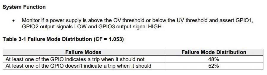
Part 1 of this series showed how the LTC2933’s safety application note provides the base failure rates based on different reliability prediction methods. With such IC’s failure rates and the readily available FMD information in the same document as shown in Figure 2, completing the system FMEDA with the IC’s information will be faster. Such a safety application note also shows the assumed system function as well as the application circuit considered wherein the IC is used.
With ADI’s safety application notes, safety analysis will be more accurate as the information comes straight from a component manufacturer as opposed to just allocating the entire failure rate to lambda dangerous or assuming a certain FMD from a specific assumption.
Conclusion
This article begins by providing an overview of a safety analysis tool called an FMEA and its variations—FMECA and FMEDA. It then delves into an example FMEDA, illustrating how incorporating a diagnostic function and its diagnostic coverage improves the SFF of a power supply circuit. The article further underscores the importance of reducing the dangerous undetected failure rate, taking diagnostics into account. Finally, this article demonstrates how system integrators can utilize component FMD information found in ADI’s safety application notes to enhance the technical accuracy of their system FMEDA and safety analysis.
References
1 “IEC 60812:2018. Failure Modes and Effects Analysis (FMEA and FMECA).” International Electrotechnical Commission, 2018.
2 Paddy Healy. “What Is a FMEDA?” Exida, April 2023.
3 “IEC 61508 All Parts, Functional Safety of Electrical/Electronic/Programmable Electronic Safety-Related Systems.” International Electrotechnical Commission, 2010.
4 Loren Stewart. “Back to Basics 17 - PFH.” Exida, November 2019.
