Supplement the MAX6948 WLED (white-LED) Driver with External PWM Control
Abstract
This application note explains how to add external PWM (pulse-width modulation) intensity control to supplement a device's internal PWM. The MAX6948 WLED (white-LED) driver serves as the example device. Configuration settings and performance data are shown.
MAX6948 Overview
The MAX6948 WLED (white-LED) driver accepts input voltages between +2.7V to +5.5V and boosts the output voltage up to +28V to drive the backlight in cell phones. If the nominal forward voltage of a WLED is 3V, then the MAX6948's 28V-rated high-voltage port can be used to drive 9 WLEDs in series for cell-phone LCD screen backlighting. This high-voltage port provides a stable current of up to 30mA. The intensity of these serial backlighting LEDs is controlled through a 10-bit, 1024-step PWM mechanism.
The MAX6948 has five other general-purpose ports that can also drive LEDs directly from the battery or be used as open-drain I/Os. When used as LED drivers, these 8V-rated ports provide a constant current of either 10mA or 30mA (max) with 8-bit, 256-step PWM intensity control.
The MAX6948 is an integrated device that generates the PWM for driving different LED intensities with I2C commands. The boost output that drives the WLEDs can be fully on, fully off, or PWMed with 10 bits. The maximum current is decided by the feedback resistor, RB. If RB is 3.3Ω, the maximum current through the LEDs is approximately 30mA  30mA).
Adding External PWM Control
Some cell-phone processors have a PWM output for direct LED intensity control. Using that output, then the external PWM signal and I2C commands can both be used for LED intensity control for different purposes. The MAX6948 does not have an external PWM signal input, but the circuit (Figure 1) can be configured to add direct external PWM intensity control.

Figure 1. Circuit used to apply external PWM Control to the MAX6948 WLED driver. PWM from a microcontroller at 5kHz is applied with duty cycles from 0 to 100%.
In this approach, the PWM control signal comes from a MAXQ2000 microcontroller EV (evaluation) board. The circuit's output voltage ranges from 0V to +3.3V; the frequency is 5kHz; the duty cycle can be adjusted from 0% to 100%. The MAX6948 is on its EV board and a Vishay® SI4800BD n-FET transistor was used to modulate the feedback resistance. For cell-phone applications, a smaller size n-FET transistor with a low drain-to-source resistance, RDSON, should be used. Otherwise the resistance of RB can be reduced to compensate for the larger RDSON. The SI4800BD has very low on-resistance, but comes in an 8-pin SO package. Because of the low 5kHz PWM switching frequency, the gate charge has a negligible effect when the MAXQ2000's drivers are used. The power consumption on the transistor is negligible because both switching and current pass through it. Figure 2 shows the experiment's setup.

Figure 2. The experiment setup with the MAXQ2000-KIT on the left and the MAX6948 on its board at the right.
Test Results
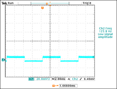
Figures 3 through 5 were captured using a current probe, and show the currents passing through the series WLEDs. The MAX6948's internal PWM function was on and its duty cycle was set to 50%. Figure 3 shows the LED current with an external PWM duty cycle of 15%; Figure 4 shows the current with an external duty cycle of 85%. Figure 5 shows the effect of the external PWM on the current through the WLEDs in series.
The data show that, due to the time constant and the feedback behavior of the MAX6948, the LED current level is not switched between the lowest current level determined by the 30Ω resistor and the highest level determined by the 3.3Ωresistor. The average amplitude and the PWM swing change according to the external PWM duty-cycle settings.

Figure 3. LED current with a 15% external PWM duty cycle.

Figure 4. LED current with an 85% external PWM duty cycle.

Figure 5. Details of the external PWM effects.
The external PWM control in this case is delivered by changing the instant and average resistance of the n-FET transistor. This, in turn, changes the current going through the series LEDs. There are two important facts to note about this configuration. First, the external PWM frequency of 5kHz is much higher than the internal frequency of 125Hz. Second, the external PWM control is also regulating the DC potion of the LED current. Because of these two features, the common "beating" problem associated to dual-PWM intensity control is avoided. External PWM control of varied duty cycles has been applied with internal PWMs from 0% to 100%, and the external control is effective. No beating is observed in different duty-cycle settings.
The luminescence of an LED varies linearly with the forward current over a limited section. Figure 6 plots the WLED luminous intensity versus forward current for the Kingbright® WLED used on the MAX6948 EV board. Modulating RB resistance between 3.3Ω and 30Ω produces a forward current between 30mA and 3.3mA. The current-to-luminescence relationship in the region between 3mA to 30mA is close to linear, as Figure 6 shows. A 0% external PWM duty cycle produces the luminous intensity at 3mA, and a 100% duty cycle at 30mA. These results assume that the internal PWM intensity is fully on. The intensity level can be adjusted lower with the device's internal PWM control by using I2C PWM commands.

Figure 6. Luminescence and current relationship.


