PCB Space-Constraint Woes Eliminated by 2 MHz, Monolithic, Buck-Boost DC-to-DC Converter and LED Driver
PCB Space-Constraint Woes Eliminated by 2 MHz, Monolithic, Buck-Boost DC-to-DC Converter and LED Driver
Nov 1 2019
Introduction
As the size of electronic devices shrink, the circuitry inside them must do the same. This trend towards product miniaturization is evident across all industries and creates new design challenges for engineers tasked with fitting solutions in space-constrained designs.
To meet increasingly stringent size requirements for compact electronic devices, integrated circuit (IC) designers bring external components inside of their devices to minimize the external component count. Of the various circuits required to build any electronic device, dc-to-dc converters are as challenging to shrink in size as they are ubiquitous—everything needs power—as power supply designers often face the reality that shrinking solution size typically negatively affects performance.
For instance, one way to save significant PCB real estate is to use a monolithic dc-to-dc converter that integrates carefully selected power switch devices within the IC package, reducing required external components to a few passive devices. In many cases, the resulting compact design brings the undesirable result of increased power loss in a smaller space for much higher temperature rise when compared with external power switch controller designs. Selecting the right monolithic dc-to-dc converter is critical in designing a power system that is both compact and efficient in order to avoid generating problematic levels of heat.
2 MHz, Monolithic, 4-Switch Buck-Boost DC-to-DC Converter and LED Driver
The LT3942 is one of Analog Devices’ most versatile monolithic buck-boost regulator ICs. This step-up/step-down converter meets the challenge of creating a flexible and compact dc-to-dc converter solution without sacrificing performance. The LT3942 integrates four 40 V/2 A power switches, two gate driver bootstrap diodes, and all its control and driver circuitry into a small 4 mm × 5 mm QFN package. With the ability of operating at up to 2 MHz switching frequency, external component sizing is kept to a minimum, conserving PCB space as well as providing high bandwidth operation for any dc-to-dc converter.
The LT3942 shares the same peak current-mode control scheme used by the LT8390A/LT8391A family of buck-boost controller ICs and exhibits seamless transitions between 2-switch boost (step-up), 4-switch buck-boost (step-up/step-down), and 2-switch buck (step-down) modes of operation. The converter observes and compares its input and output voltages to determine the correct mode of operation. As the ratio of PVIN:PVOUT changes and forces the converter to mode transition, the LT3942 maintains regulation while it intelligently shifts control between switch pairs.
In addition to regulating the output voltage over a variety of PVIN:PVOUT combinations, the LT3942 can also be configured to regulate input or output current for use in constant current regulation applications. Current monitoring feedback from the ISMON pin provides a buffered voltage output proportional to the measured current, allowing connected circuitry to inspect the measured current levels. This ability to regulate current or voltage makes the LT3942 perfect for use as an LED driver, compact battery charger, miniature solar panel-powered converter, or general-purpose voltage regulator.
14 V, 1 A LED Driver
Figure 1 shows a complete evaluation circuit for an LT3942-based compact LED driver. This solution is capable of providing 1 A to a string of four (up to 14 V) white LEDs connected in series. The maximum power delivery input voltage range is 7 V to 36 V, with reduced current operation down to 4 V, which is ideal for unregulated automotive input supplies. The LT3942 in this solution operates at a 2 MHz switching frequency, enabling the use of relatively small inductors and capacitors. The result is that the entire LED driver solution fits a 15 mm × 15 mm PCB footprint, with all components placed on the one side of the board, including the IC.
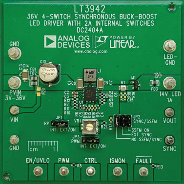
Figure 1. This LT3942-based demonstration circuit (DC2404A) showcases a high performance, compact dc-to-dc regulator solution specifically for, in this case, driving LEDs.
This solution also boasts high bandwidth operation, allowing for quick adjustments of the output current. While in buck operation, the LT3942 achieves dimming ratios as high as 5000:1 using an external PWM source to dim the LEDs at a flicker-free 100 Hz. If an external PWM source is not available, the LT3942 can also be dimmed using its internal PWM dimming feature. Internal dimming provides up to 128:1 dimming without the need for any external PWM signal source, requiring only a single resistor to set dimming frequency and a dc voltage to control the duty cycle of the output current. Like most Power by Linear™ LED drivers, the LT3942 also features analog dimming by applying a dc voltage at the CTRL pin for up to 20:1 analog dimming. Analog and PWM dimming can be combined to achieve higher effective dimming ratios than either method can alone.
Spread Spectrum Frequency Modulation Reduces EMI Peaks
To help create a low noise dc-to-dc converter system, the LT3942 includes an optional spread spectrum frequency modulation (SSFM) feature. When enabled, SSFM sweeps the switching frequency between the value set by the RT resistor up to 25% additional switching frequency. This sweeping action distributes the emissions caused by switching over a broad spectrum of frequencies rather than concentrating those emissions into narrow bands, reducing EMI peaks overall. SSFM, when used in combination with input and output EMI filters, can help reduce EMI over a wide range of frequencies, making it easier to design an emissions-compliant system.
12 V, 1 A Voltage Regulator
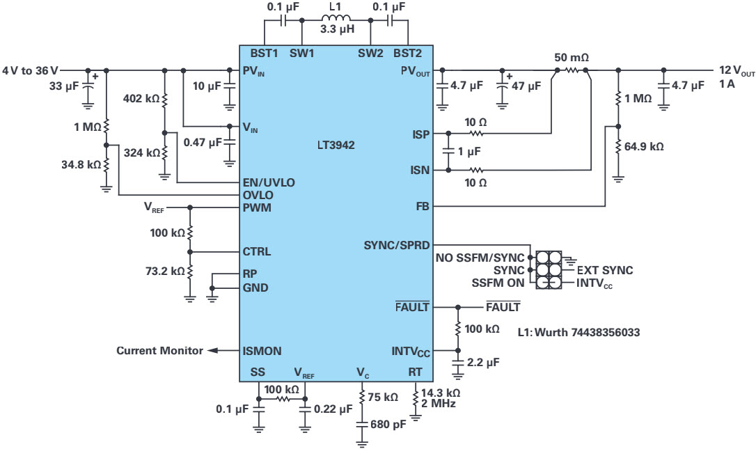
The LT3942 is not limited to driving LEDs. It is a capable, compact voltage regulator, well suited to solve the problem of producing stable outputs from wide-ranging, unregulated power sources. The 12 V, 1 A voltage regulator design shown in Figure 4 is similar to the 14 W LED driver solution in Figure 2, with a few small modifications. Like the LED driver application, the voltage regulator can maintain output regulation over a wide input voltage range, delivering full output power as low as 7 V and maintaining operation as low as 4 V with reduced output power.
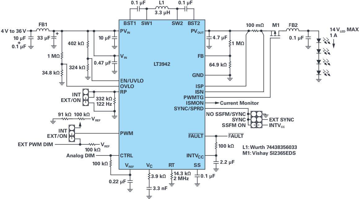
Figure 2. DC2404A utilizes the LT3942 to create a compact 14 W LED driver application capable of providing regulated output current over a wide input range.
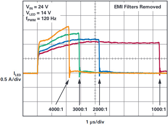
Figure 3. The LT3942’s high bandwidth operation helps achieve high ratio PWM dimming for LED lighting applications with wide dynamic brightness ranges. With EMI filters removed, DC2404A achieves up to 4000:1 dimming at 120 Hz and as high as 5000:1 dimming at 100 Hz.
The efficiency curves in Figure 4 show that even when operating at a 2 MHz switching frequency, the LT3942 12 V regulator boasts an impressive peak efficiency of nearly 95%, with most of its input voltage range exhibiting efficiencies of 85% and above. Over 80% efficiency is maintained even when powering its output at a tenth of its total output power, demonstrating its ability to operate efficiently in light load conditions.
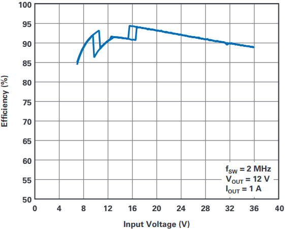
(a). Input Voltage Efficiency Sweep.
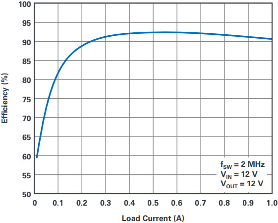
(b). Load Current Efficiency Sweep.
Figure 4. Configured as a 12 W voltage regulator, the LT3942 exhibits excellent line and load efficiency properties over a wide input range.
The LT3942’s current sensing and control feature is geared toward LED dimming control, but it serves well in other situations requiring both voltage regulation and current control. When the sensing resistor is configured at the output, the LT3942 can easily be configured to act as a compact constant-current, constant-voltage battery charger. For applications that have strict input current limitations, such as circuitry powered from small batteries, capacitor banks, or photovoltaic cells, the sensing resistor can be moved to the input side of the regulator, providing an input current limit to the system, as well as monitoring. The LT3942 seamlessly transitions from CC mode to CV mode (and vice versa), ensuring regulation of input and/or output at all times.
Automotive Sequential Turn Signal and Trim Lighting
Animated sequential turn signal lights commonly seen on newer luxury and performance cars are quickly gaining popularity, replacing the traditional blinker style indicators. Early implementations of the sequential turn signal use multiple step-down converters or linear regulators to power LEDs in the turn signal clusters, resulting in complex, relatively inefficient, and excessively large solutions, greatly limiting the field of possible lighting designs. Reducing the quantity of required power ICs to one efficient device is an obvious way to expand the range of a lighting designer’s options.
A single converter solution requires a device that is capable of maintaining output regulation across the various LED combinations—hence, string voltages, that occur in the lighting design: from every LED on, to a single LED on, to all the other combinations in between. As the animated lights move through the configurations of connected LEDs, the input voltage can be higher than, lower than, or equal to the output voltage. This type of application requires a step-up/step-down converter that can intelligently select and seamlessly transition between modes of operation while maintaining output regulation. The LT3942’s buck-boost topology and high bandwidth operation enable it to easily navigate these changes without glitches.
The sequential turn signal design seen in Figure 5 uses the LT3942 to power eight LEDs at 330 mA from an automotive battery and selects between powering either an amber string of LEDs, for turn signal operation, or a white string, for daytime-running lights or other trim lighting used in headlight/taillight designs.
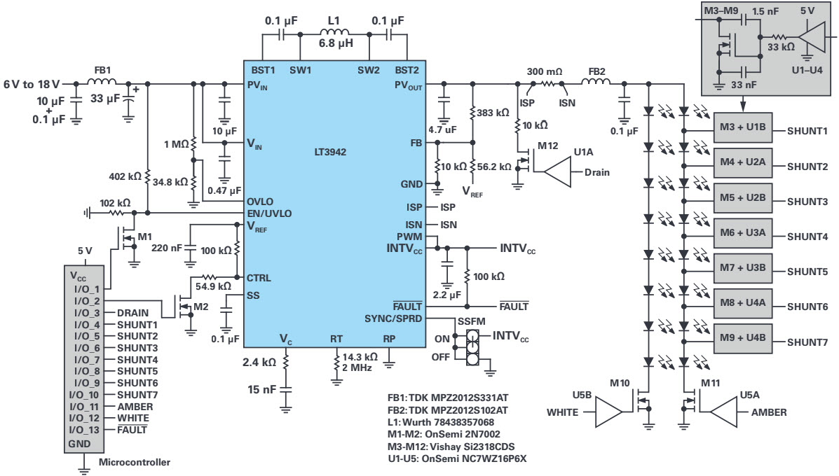
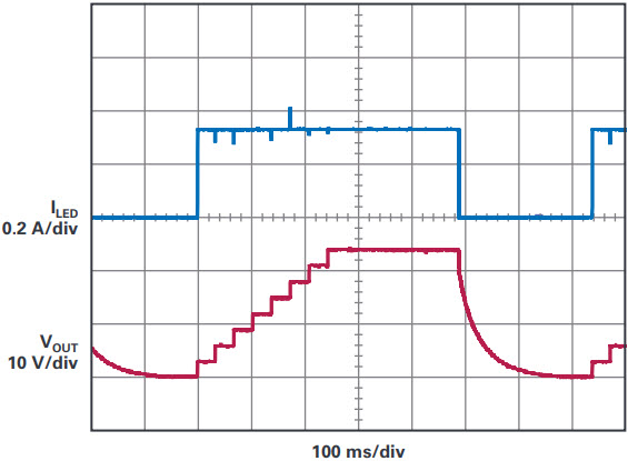
Figure 5. LEDs are turned on one at a time in sequential turn signal applications, forcing the dc-to-dc converter to rapidly adjust to new PVIN:PVOUT combinations. This is no problem for the LT3942, which seamlessly transitions from boost, to buck-boost, to buck operation during the sequential turn pattern, ensuring regulated LED current across the modes.
A microcontroller acts as an interface between the turn signal input from the user and the lighting system. This gives the lighting designer (or end user, if desired) complete control of all the timing and signals necessary to perform the animated sequential turn-on of the LEDs, as well as control over which color LED string is powered at any given time.
In this design, during the sequential turn-on pattern, the turn signal LEDs are introduced to the string one at a time to produce the turn signal. As LEDs are added to the string by the microcontroller, the LT3942 maintains regulation of the output current for consistent light brightness. After all LEDs are illuminated, the LT3942 stops switching operation and the output voltage is drained to set the converter up for the next sequential turn-on cycle. When the turn signal is not being used, the microcontroller reconnects the trim lighting LED string and continues to wait for turn-signal user input, combining two lighting functions into a single LED driver solution.
Summary
Electronic devices continue to force engineers to reach for smaller integrated devices to meet increasingly limited space requirements. The LT3942 monolithic buck-boost converter and LED driver addresses space-constrained electrical designs by integrating a number of space-saving features without compromising performance. Its monolithic design and 2 MHz switching frequency operation shrinks solution size, enabling it to squeeze into cramped PCB designs. It is highly flexible—able to operate as both a constant current and constant voltage regulator—enabling it to fit a wide variety of applications.
For designs that require low noise power supplies to meet stringent EMI requirements, the LT3942’s SSFM feature helps bring down conducted and radiated emissions, and its convenient IC package pinout allows for compact switching hot loops. These features, plus a wide input range, simplify a designer’s life when faced with compact power requirements.
About the Authors
Kyle Lawrence is an applications engineer at Analog Devices. He is responsible for the design and testing of a variety of dc-to-dc converters, including 4-switch buck-boost voltage regulators and LED drivers targeting low ...


