LT1785 and LT1791: 60V, Fault-Tolerant RS485/RS422 Transceivers
LT1785 and LT1791: 60V, Fault-Tolerant RS485/RS422 Transceivers
Jun 1 1999
Introduction
The LT1785 and LT1791 RS485/RS422 transceivers with ±60V fault tolerance solve a real-world problem of field failures in RS485 interface circuits. RS485 and RS422 data networks are used in a wide variety of data-communications applications. Modems and other computer peripherals use point-to-point RS422 connections to support higher communications speeds with better noise immunity over greater distances than is possible with RS232 connections. Multipoint RS485 networks are used for LANs and industrial-control networks. These applications are vulnerable to the unknown, sometimes hostile environment outside of the controlled, shielded environment of a typical electrical-equipment chassis. Data line voltages exceeding the absolute maximum ratings of the transceiver chips can cause field failures of conventional transceiver circuits. Installation wiring faults, ground voltage faults and lightning-induced surge voltages are all common causes of overvoltage conditions that can damage conventional interface circuits. The rate of field failures in RS485 transceiver chips in some high-risk environments is so high that the transceiver chips are often DIP packages mounted in sockets to allow easy field servicing of equipment. The high voltage fault tolerance of the LT1785 and LT1791 provides a highly reliable solution for data networking in high-risk environments.
In addition to enhancing network-system fault tolerance, the electrical performance of the LT1785 and LT1791 matches or exceeds the best performing standard RS485/RS422 transceivers available, at data rates of up to 250kbaud. The LT1785 and LT1791 transceivers feature high input impedance for extended data networks, slew controlled outputs for EMI control, low impedance cable-drive capability, fail-safe receiver design and on-chip ±15kV ESD protection. With industry standard pinouts, systems can be easily upgraded for improved environmental fault tolerance.
Inherently Safe Up to ±60V
The electrical standards for RS422 and RS485 requires receivers and unpowered transmitters to operate with input common mode voltages from −7V to 12V, even though transmit voltages are limited to a voltage range between ground and 6V. This extra common mode range allows some tolerance for the real-world problem of ground voltage differences across a network. Unfortunately for most transceivers, voltages far in excess of the −7V to 12V range may occur in an actual network.
The RS485 and RS422 transceivers commonly available from several vendors are all vulnerable to damage from fault voltages only slightly outside the −7V to 12V operating envelope. One vendor’s RS485 transceivers have absolute maximum voltage ratings of −8V to 12.5V on the data I/O pins. Such narrow margins above the required −7V to 12V operating conditions makes such circuits very fragile in a real-world environment. In addition, external protection circuitry is ineffective at protecting these circuits without interfering with normal operating signal levels.
The LT1785 and LT1791, with ±60V ratings on the driver output and receiver input pins, are inherently safe in environments that will destroy other interface circuits. Whether the circuit is transmitting, receiving, in standby or powered off, any voltage within ±60V will be tolerated by the chip without damage. Data communication will be interrupted during the fault condition, but the circuit will live to talk another day. The I-V curves shown in Figures 1–3 illustrate this.
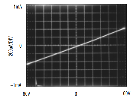
Figure 1. I–V curve of LT1791 receiver input: −60V to 60V.
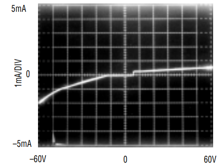
Figure 2. I–V curve of LT1791 driver output: VCC = 5V, DE = 0V, −60V < VOUT < 60V.
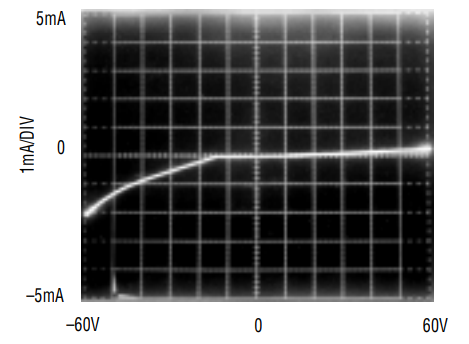
Figure 3. I–V curve of LT1791 driver output: VCC = 0V, DE = 0V, −60V < VOUT < 60V.
The LT1785 and LT1791 receiver inputs maintain high impedance, typically 120kΩ, from −60V to 60V (see Figure 1). This benign characteristic is present under all operating conditions. Data signals are properly received only in the −7V to 12V common mode range of RS485, but no damage to the LT1785/LT1791 will result over the entire ±60V range.
The driver behavior of the LT1785/LT1791 is more involved than the receiver inputs and must be discussed separately for each operating mode. Figure 2 shows the I-V characteristic of the LT1791 driver outputs with the drivers in high impedance mode. Below −12V, some leakage current flows, but this only reaches a 2mA magnitude at −60V. With VOUT > VCC (5V in this case), a small (100µA) current is conducted, which stays virtually constant as VOUT increases up to 60V. With VCC = 0V, the driver I-V curve is the same for negative voltages, but the 100µA current with positive voltages is not present (Figure 3).
Fault conditions while the circuit is transmitting cause the driver to enter current limit. For large magnitude faults, the current limit folds back to near zero. If short-circuit fault conditions are sustained, a thermal shutdown circuit will turn the drivers off. Figures 4 and 5 show the driver I-V curves for the outputs in low and high states.
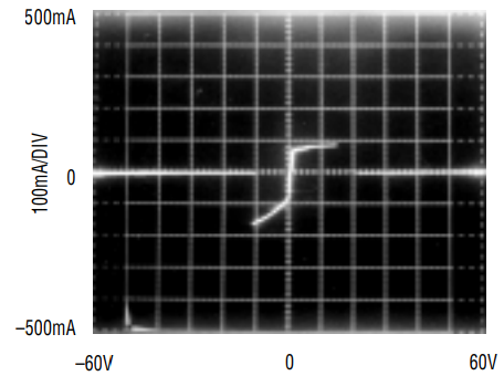
Figure 4. Driver fault current for output low (DE = VCC = 5V).
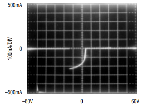
Figure 5. Driver fault current for output high (DE = VCC = 5V).
Extending Beyond ±60V
Although ±60V fault tolerance forgives a great number of sins, higher voltage demons may still be lurking. ESD is one such demon, with voltage spikes of thousands of volts. The LT1785 and LT1791 have on-chip ESD protection to prevent damage from ESD transients of up to ±15kV. The ESD protection devices shunt the ESD energy away from active circuitry to the ground and VCC supply pins. For the ESD protection to function properly, the user must ensure that low ESR supply-decoupling capacitors are located close to the VCC and ground pins of the circuit. 0.1µF ceramic chip capacitors work well.
Other high voltage faults, such as lightning induced surge voltages, industrial environment ground loops or shorts to the AC line, are not as limited in energy as ESD transients. For such high energy faults, external protection must be used to protect the circuits. Typical protection networks use voltage clamping combined with current limiting networks. In concept, such networks could be used with most RS485 circuits to afford extended protection, but in practice, the addition of protection networks interferes with normal operation of the data network. Voltage clamping Zeners or TransZorbs® are not available in tight voltage tolerances and in addition, their internal impedances create several volts of additional potential above their nominal breakdown voltage to appear at the protected device’s pins when fault currents flow. To protect a circuit with a −8V to 12.5V absolute maximum voltage rating would require the use of protection devices with voltage ratings much below the required common mode range of RS485 networks. The triggering of the protection diodes would interrupt normal data transmission. The huge margin between operating voltages and the ±60V absolute maximum limits makes external protection a viable option with the LT1785 and LT1791.
Figure 6 shows an example of the use of external clamping and limiting components to extend the LT1785’s ±60V inherent tolerance to much higher ±170V levels, the peak 120VAC line voltage in this example. 36V TransZorbs are used to clamp the transceiver line pins below the 60V rating of the transceiver. During a short to the 120VAC line, peak surge currents of nearly 3A will flow through the 47Ω resistors and the PolySwitch™ limiters. The peak current rating and series resistance of the TransZorbs must be considered during selection to ensure that the clamp limiter can withstand the surge and that the peak voltage will remain below the ±60V rating of the LT1785. At 3A, even high current TransZorbs will exceed their nominal breakdown voltage by several volts, making this protection method ineffective with transceiver circuits with only 1V to 4V absolute maximum margin above their operating ranges. The PolySwitch limiters are thermally activated and increase in resistance by many orders of magnitude in about 10ms. After the PolySwitch transition, fault currents are only a few milliamperes. Carbon composite resistors must be used for limiting the initial surge current before the PolySwitch transition point. Metal film resistors do not have effective surge overload ratings and will fail before the PolySwitch transition drops the currents to sustainable levels.
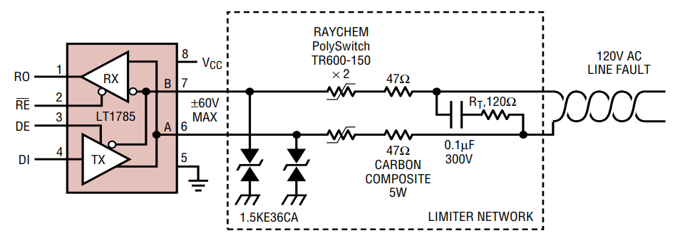
Figure 6. Fault tolerance extended to 120VAC line voltage.
Electrical Features Enhance Large Network Data Integrity
In addition to their unique fault tolerance capabilities, these transceivers provide electrical performance features that maximize the integrity of data transmission over long-line, distributed networks. Controlled-slew-rate outputs minimize EMI and cable reflection problems. Limited slew rates restrict data rates up to a maximum of 250kbaud (Figure 7), but this is not a limitation in most networks. RS485 standards allow data rates faster than 250kbaud only on small networks, less than 1000 feet in length. Controlled slew rates reduce cable reflections caused by connection stubs, imperfect terminations and cable splices, improving data transmission integrity on most networks.
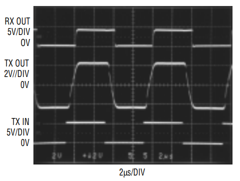
Figure 7. Normal operational waveforms at 250kbaud.
LT1785 and LT1791 driver outputs have extra drive capability compared to most competing transceivers. Output levels are guaranteed when driving low impedance loads—as low as 36Ω. The extra current drive allows inexpensive telephone cable, with characteristic impedance as low as 72Ω, to be used for the networking cable. This can result in significant cost savings in large networks and allows the use of existing wiring in many buildings.
A-grade devices are available that ensure fail-safe receiver outputs when the inputs are opened or shorted or no signal is present. The receiver thresholds on the LT1785A and LT1791A are guaranteed to be between 0.01V and 0.200V. This is tighter than the RS485/RS422-standard −0.200V to 0.200V thresholds. The guaranteed positive voltage thresholds eliminate ambiguous received signals during system fault or standby conditions. Open cables, shorted cables or all drivers in high impedance mode result in a zero volt differential at the receiver. The fail-safe receiver feature simplifies the design of software to detect these conditions. Any receiver-output low condition will be reliably interpreted as valid data.
The LT1785 and LT1791 feature extra high receiver input impedance, 85kΩ minimum, to minimize dataline loading and allow up to 128 connections on a data network. Standard RS232 networks are limited to 32 receivers, where each receiver is considered to be one “unit load.” Each LT1785 or LT1791 may be counted as 1/4 unit load and mixed with other 1-unit-load transceivers in a network. Maximum network size is reached at a total of 32 unit loads.
These electrical features, combined with rugged overvoltage tolerance, make the LT1785 and LT1791 excellent choices for extended data networks in less-than-benign electrical environments (Figure 8). Any data network operating in industrial environments, subject to installation errors or any other wiring faults, will benefit from using these transceivers for trouble-free, reliable data networking.

Figure 8. Half-duplex RS485 network operation.
TransZorb is a registered trademark of General Instruments, Inc. PolySwitch is a trademark of Raychem Corp


