Abstract
When a factory goes down, it is a critical event that must be addressed immediately. Protection circuitry that is used to mitigate system faults has traditionally been bulky, expensive, and difficult to implement. However, as this application note discusses, advances in modern protection circuits now provide system engineers with robust, highly integrated, and easy-to-implement solutions that guard against electrical stress-related problems and, as a result, help maintain system uptime.
Introduction
Left unaddressed, system faults can damage equipment, or worse, take down an entire factory. Consider an area that gets hit by frequent lightning strikes. Oklahoma, for example, experiences, more than one million strikes per year on average, according to Vaisala's U.S. National Lightning Detection Network. The top state in this regard is Florida, which averages 25.3 lightning strikes per square mile and 1.45 million strikes each year1. Each lightning strike can weaken the system and eventually take it down after one or several strikes. Therefore, areas that experience frequent lightning strikes must make their protection systems extra robust. If a lightning strike were to take your factory offline, how would this impact your business?
Protection circuitries to safeguard against equipment-damaging faults are valuable for mitigating the effects of occurrences like lightning strikes. However, traditionally, these circuitries have been bulky, expensive, and difficult to implement. Fortunately, advances in modern protection circuits now provide system engineers with robust, highly integrated, space-saving, and easy-to-implement solutions.
The Case for System Protection
Because all electrical systems experience voltage, current, thermal, and other faults, proper protection is critical for system uptime. Neglecting protection can hamper successful completion of system designs during the design verification test stage. Or, an even worse scenario involves line-down situations on the factory floor. This application note discusses common system faults in three main areas: voltage, current, and thermal.
Voltage Faults
System Voltage Surge and Ringing
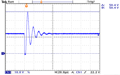
Input voltages can go higher and/or lower than the normal DC voltage range due to a number of incidents, such as lightning strikes, blown fuses, short circuits, hot-swap events, and cable ringing. Figure 1 demonstrates a short-circuit event where a brief short circuit at the end of a 10-foot cable (Figure 2) can cause its voltage to ring and peak to 50.4V, doubling its 24VDC normal voltage. The voltage also rings down to about 11V (from the initial short circuit to 0V). A system that is considered robust would continue to operate throughout this ringing without interruption or, at least, survive it without damage.

Figure 1. Long cable voltage ringing after a brief short-circuit condition.

Figure 2. Test circuit schematic.
Similar voltage ringing can happen during a couple of other scenarios: a hot-swapping event where a card with a discharged capacitor is plugged into a live backplane (Figure 3), or a blown fuse elsewhere in the system. The situation worsens if the system DC voltage has a wide range. For example, IEC 61131-2 defines an industrial programmable logic controller (PLC) with 24VDC nominal rail voltage plus -15% to +20% tolerance and +5% peak AC component on top of it. So, the 24VDC rail can be at 19.2VDC minimum and 30VDC maximum. If we start with 30VDC power source in the above experiment, the peak ringing voltage would easily reach 60V.

Figure 3. Hot swapping a system card.
A lightning strike can cause a high-energy surge voltage that is typically handled by a front-end transient voltage suppressor (TVS) device and input filter. In a 24V bus system, an industrial system typically uses a device like the STMicroelectronics® SMAJ33A to clamp it. Under surge conditions, this TVS device can clamp the surge voltage to 53.3V maximum. So, any electronic component connected to this 24V bus must be able to withstand at least 53.3V.
Input Reverse Voltage
System miswiring is rare but, nonetheless, can occur. For example, in a rack-mount system, a person might plug in a card in reverse or connect the power cable with the wrong polarity. When the input voltage drops suddenly (the input is shorted or rings low), the output capacitor is now at a higher potential, which causes a reverse-voltage condition. A reverse-voltage condition can also happen when the output is suddenly shorted to a higher voltage rail (in a bundled cable, for example). While input reverse-voltage faults are rare, when they do happen, they can cause costly system damage.
Current Faults
Overcurrent/Short-Circuit Fault
Output overloading and short circuiting are two obvious current faults. Overcurrent loading is triggered when the system runs overcapacity. As for a short circuit, this can be caused by a faulty component on a board. Or, a bad short circuit could happen if someone accidentally drops a wrench onto the power connector or drills into a cable bundle. Unprotected boards can suffer permanent damage or, worse, catch on fire. Figure 4 displays a board burned as a result of a short circuit.

Figure 4. Board burned due to short circuit.
Inrush Current
When a board with a discharged capacitor is plugged into a live backplane, a surge of current rushes in to charge up the capacitor. Uncontrolled, this inrush current will follow this equation:
I = Cxdv/dt
Where:
I = inrush current
C = capacitance
dv/dt = rate of change of the capacitor voltage over time
If a discharged capacitor (at 0V) is plugged into a live backplane at 24V, dV/dt in this case is instantaneous (infinite), translating to I = infinite. Without inrush control, this infinitely high current spike can damage connectors, blow up fuses, and cause voltage ringing on the backplane voltage.
Reverse Current
When a reverse voltage event occurs, as explained in the Input Reverse Voltage section, current flow in the reverse direction can cause severe damage to the system.
Thermal Faults
Overtemperature Protection
To prevent damage and potential fire-related problems, overtemperature protection shuts down the system when its temperature, or that of one of its components, reaches a dangerous level. If designed properly, a system should be able to operate without ever going into overtemperature shutdown. But a primary fault condition—such as an extended overload condition, failed or failing system fan, accidental blocking of the system air inlet/outlet, or failure of the room A/C—can trigger an overtemperature shutdown.
Thermal Protection
Compared to an overtemperature shutdown, thermal protection has more intelligence. When the temperature rises higher than normal during operation due to a primary fault, thermal protection provides the system a warning and also some choices. For example, the system can choose to shed noncritical loads, running at a lower switching speed to dissipate less power. As a result, the system might be able to avoid an overtemperature shutdown with reduced system performance until the primary fault has been resolved.
System Protection Solution
Design Challenges
System engineers who want to fully protect their products face some design challenges. A discrete or partly integrated IC implementation calls for many external components. The tolerances stack up of the components is tedious to analyze, and it is also difficult to verify and guarantee performance over time. With the multiple components, the resulting solution is large.
Key Features of Newer System Protection ICs
In an ideal world, a system protection solution will be highly integrated, easy to design-in, and easily pass design qualification. Some key features to seek in a modern protection IC include:
- Integrated pFET and nFET for forward/reverse voltage/current protection
- Integrated precision current sensing
- Programmable UV/OV, current-limit thresholds, and fault response modes
- Thermal protection with warning flags
Example of a Modern System Protection Solution
To protect the example system against all of the circuit faults discussed, we selected the MAX17608/MAX1709 current limiters. These devices are the industry’s most highly integrated, space-efficient, robust ICs for high-voltage protection at 1A load current. These current limiters address both the increasingly stringent machine safety standards and the need for smaller solutions as modular rack PLCs continue to shrink and become denser with greater I/O capability.

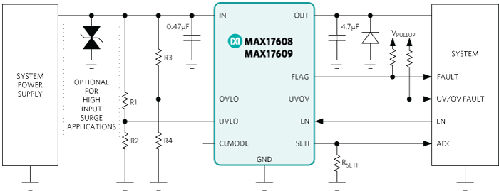
Figure 5. The MAX17608/09 are highly integrated, space-efficient protection ICs.
Figure 5 shows the MAX17608/09 application circuit schematic. These ICs operate from +4.5V to +60V and can withstand negative input voltage to -65V. They integrate a pFET and nFET for forward/reverse voltage/current protection, programmable UV/OV, current-limit thresholds and fault response modes, and thermal protection with warning flags. The solution size is very small, as the ICs come in a tiny 3mm x 3mm, 12-pin TDFN-EP package.
Along with all of the desirable integrated features, these current limiters have very precise current sensing at ±3%. A discrete solution can typically provide ±20%, so this is a significant performance improvement. The voltage on the SETI pin also provides monitoring of system current consumption.
Summary
Faults happen, but by implementing the proper circuit protection in your system, you can prevent problems on the factory floor. Compared to their predecessors, today’s advanced protection ICs offer robust features in small packages, ideal for protecting systems against voltage, current, thermal, and other faults.
Related to this Article
Products
4.5V to 60V, 1A Current Limiter with OV, UV, and Reverse Protection
Adjustable Overvoltage and Overcurrent Protectors with High Accuracy
High-Accuracy, Adjustable Power Limiters
4.2V to 36V, 1A Current Limiter with OV, UV, Reverse Voltage Protection
Adjustable Overvoltage and Overcurrent Protectors with High Accuracy
High-Accuracy, Adjustable Power Limiter
High-Accuracy, Adjustable Power Limiters
High-Accuracy, Adjustable Power Limiter
High-Accuracy, Adjustable Power Limiter
4.5V to 60V, 1A Current Limiter with OV, UV, and Reverse Protection
High-Accuracy, Adjustable Power Limiter
4.5V to 60V, 1A Current Limiter with OV, UV, and Reverse Protection
High-Accuracy, Adjustable Power Limiters
Adjustable Overvoltage and Overcurrent Protectors with High Accuracy


