Compensate for Wire Drop to a Remote Load
A common problem in power distribution systems is degradation of regulation due to the wire voltage drop between the regulator and the load. Any increase in wire resistance, cable length or load current increases the voltage drop over the distribution wire, increasing the difference between voltage at the load and the voltage programmed by the regulator. Remote sensing requires routing additional wires to the load. No extra wiring is required with the LT6110 cable/wire drop compensator. This article shows how the LT6110 can improve regulation by compensating for a wide range of regulator-to-load voltage drops.
The LT6110 Cable/Wire Compensator
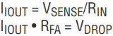
Figure 1 shows a 1-wire compensation block diagram. If the remote load circuit does not share the regulator’s ground, two wires are required, one to the load and one ground return wire. The LT6110 high side amplifier senses the load current by measuring the voltage, VSENSE, across the sense resistor, RSENSE, and sinks a current, IIOUT, proportional to the load current, ILOAD. IIOUT scale factor is programmable with the RIN resistor from 10µA to 1mA. Wire voltage drop, VDROP, compensation is accomplished by sinking IIOUT through the RFA feedback resistor to increase the regulator’s output by an amount equal to VDROP. An LT6110 cable/wire voltage drop compensation design is simple: set the IIOUT • RFA product equal to the maximum cable/wire voltage drop.


Figure 1. No extra wires are required to compensate for wire voltage drop to a remote load.
The LT6110 includes an internal 20mΩ RSENSE suitable for load currents up to 3A; an external RSENSE is required for ILOAD greater than 3A. The external RSENSE can be a sense resistor, the DC resistance of an inductor or a PCB trace resistor. In addition to the IIOUT sink current, the LT6110 IMON pin provides a sourcing current, IMON, to compensate current-referenced linear regulators such as the LT3080.
Compensating Cable Voltage Drops for a Buck Regulator
Figure 2 shows a complete cable/wire voltage drop compensation system consisting of a 3.3V, 5A buck regulator and an LT6110, which regulates the voltage of a remote load connected through 20 feet of 18 AWG copper wire. The buck regulator’s 5A output requires the use of an external RSENSE.

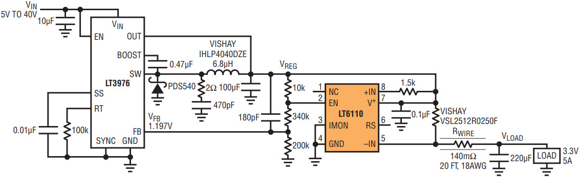
Figure 2. Example of a high current remote load regulation: a 3.3V, 5A buck regulator with LT6110 cable/wire voltage drop compensation.
The maximum 5A ILOAD through the 140mΩ wire resistance and 25mΩ RSENSE creates an 825mV voltage drop. To regulate the load voltage, VLOAD, for 0A ≤ ILOAD ≤ 5A, IIOUT • RFA must equal 825mV. There are two design options: select IIOUT and calculate the RFA resistor, or design the regulator’s feedback resistors for very low current and calculate the RIN resistor to set IIOUT. Typically IIOUT is set to 100µA (the IIOUT error is ±1% from 30µA to 300µA). In the Figure 2 circuit the feedback path current is 6µA (VFB/200k), the RFA resistor is 10k and the RIN resistor must be calculated to set IIOUT • RFA = 825mV.
and

so for RFA = 10k, RSENSE = 25mΩ and RWIRE = 140mΩ, RIN = 1.5k.
Without cable/wire drop compensation the maximum change in load voltage, ∆VLOAD, is 700mV (5 • 140mΩ), or an error of 21.2% for a 3.3V output. The LT6110 reduces ∆VLOAD to only 50mV at 25°C, or an error of 1.5%. This is an order of magnitude improvement in load regulation.
Precision Load Regulation
A modest improvement in load regulation with the LT6110 only requires a moderately accurate RWIRE estimation. The load regulation error is the product of two errors: error due to the wire/cable resistance and error due to the LT6110 compensation circuit. For example, using the Figure 2 circuit, even if the RSENSE and RWIRE calculation error is 25%, the LT6110 still reduces VLOAD error to 6.25%.
For precise load regulation, an accurate estimate of the resistance between the power source and load is required. If RWIRE, RSENSE and the resistance of the cable connectors and PCB traces in series with the wire are accurately estimated, the LT6110 can compensate for a wide range of voltage drops to a high degree of precision.
Using the LT6110, an accurate RWIRE estimation and a precision RSENSE, the ∆VLOAD compensation error can be reduced to match the regulator’s voltage error over any length of wire.
Conclusion
The LT6110 cable/wire voltage drop compensator improves the voltage regulation of remote loads, where high current, long cable runs and resistance would otherwise significantly affect regulation. Accurate regulation can be achieved without adding sense wires, buying Kelvin resistors, using more copper or implementing point-of-load regulators—common drawbacks of other solutions. In contrast, compensator solutions require little space while minimizing design complexity and component costs.
About the Authors


