EVAL-ADUM34XEEBZ

Overview
Features and Benefits
- Simplified evaluation of the ADuM340E/ADuM341E/ADuM342E digital isolator family
- U4 not inserted to allow evaluation of other supported iCoupler digital isolator in 16-lead SOIC_W package
- Enable controls
- Small, easy configuration optimized for rapid evaluation on breadboards/prototype boards
- Test points can be fitted to measure all signals
Product Details
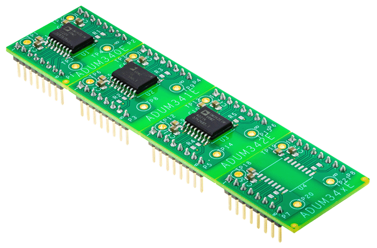
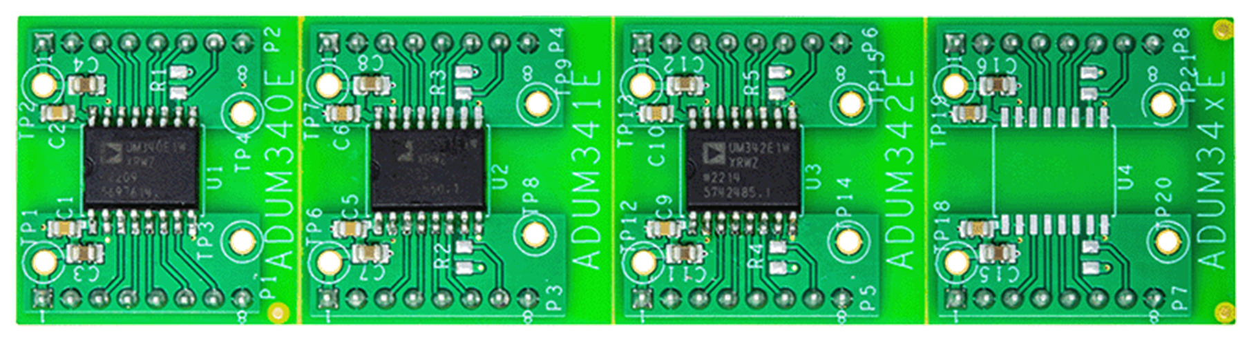
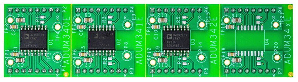
The EVAL-ADuM34XEEBZ evaluation board supports simplified, efficient evaluation of the 5.7 kV rms ADuM340E/ADuM341E/ADuM342E family of iCoupler® digital isolators. The EVAL-ADuM34XEEBZ board also grants the ability to examine multiple other 16-lead SOIC_W iCoupler digital isolators via the unpopulated U4, which provides the user a JEDEC standard 16-Lead SOIC_W pad layout and routing appropriate for the evaluation of supported devices.
The EVAL-ADuM34XEEBZ board features V shaped grooves between each component (U1 to U4) that allow the user to split the PCB into sections and examine a specific device of their choice on a breadboard or similar prototyping board for ease of use. If U4 is populated with a different supported device, refer to the appropriate device data sheet.
Power and the inputs/outputs can be connected either directly to the pin header connectors or onto a prototyping board.
Enable controls are provided via the pin headers, which can be configured via a digital input, or the user can refer to the schematic in Figure 2 in the user guide and populate the pull-up resistors on the VE1/VE2 pins. The pull-ups on the VEx pins are not inserted by default. The 100 kΩ value in the schematic may need to be changed depending on the application needs.
The EVAL-ADuM34XEEBZ board follows printed circuit board (PCB) design practices, including a ground plane on each side of the isolation barrier. No other electromagnetic interference (EMI) or noise mitigation design features are included on this board.
Full specifications for the device under test (DUT) are available in the corresponding ADuM340E/ADuM341E/ADuM342E data sheet, which must be consulted in conjunction with the user guide when using the evaluation board.
Markets and Technologies
Applicable Parts
Getting Started
EQUIPMENT NEEDED
- Oscilloscope
- Signal generator
- 2.25 V to 5.5 V supply
- Breadboard/prototype board