Overview
Features and Benefits
- 4 analog inputs
- 8 analog outputs
- Stereo S/PDIF input and output
- Self boot EEPROM
- Headers for interfacing to off board peripherals
Product Details
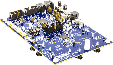
This board is suitable for the evaluation of, and software development for, the ADAU1467 and ADAU1463 SigmaDSP® processors. Note that the ADAU1467 and the ADAU1463 are functionally identical; however, the ADAU1467 has more program and data memory than the ADAU1463. When using this evaluation board to evaluate the ADAU1463, select the ADAU1463 block (see the Setting Up Communications in SigmaStudio section) rather than the ADAU1467, as shown in Figure 16. Performing this action informs the compiler to limit the amount of memory allocated to match the ADAU1463. All other procedures and instructions in this user guide are identical for the ADAU1463 and ADAU1467.
This evaluation board provides access to the digital serial audio ports of the ADAU1467. Four analog inputs and eight analog outputs are provided by the AD1937 codec included in the evaluation kit. Switches enable the evaluation of alternate features provided by many of the pins with multiplexed functionality, and numerous headers provide access to serial audio ports and the master and slave control ports. These selectable modes and headers make the EVAL-ADAU1467Z well suited to prototyping larger application circuits, as well as initial device evaluation. The ADAU1467 core is programmed using Analog Devices, Inc., SigmaStudio® software, which interfaces to the evaluation board via a USB interface (USBi). The on-board, electronically erasable programmable read only memory (EEPROM) can be programmed for self boot mode. The evaluation board is powered by a 6 V dc supply, which is regulated to the voltages required on the board. The printed circuit board (PCB) is a 4-layer design with a ground plane and a power plane on the inner layers. The evaluation board includes connectors for external analog inputs and outputs and optical Sony/Philips Digital Interface (S/PDIF) interfaces. The master clock is provided by the integrated oscillator circuit and the on-board 12.288 MHz passive crystal.
For full details, see the ADAU1467 and AD1937 data sheets, which must be used in conjunction with this user guide when using the evaluation board.
Markets and Technologies
Applicable Parts
Package Contents
- EVAL-ADAU1467Z evaluation board
- EVAL-ADUSB2EBZ (USBi) communications adapter USB cable with Mini-B plug
- 6 V ac to dc power supply
Documentation & Resources
-
EVAL-ADAU1467Z User Guide11/1/2017PDF2 M


