EVAL-AD5791ARDZ


Overview
Features and Benefits
- Full featured evaluation board for the AD5781 and AD5791
- ADP5070 power solution generated from single 5 V supply
- Various link options
- PC control in conjunction with the Analog Devices Inc., EVALSDP-CK1Z (SDP-K1) controller board
Product Details
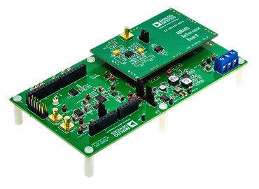
The operation of the EVAL-AD5781ARDZ or EVAL-AD5791ARDZ for the AD5781 (18-bit) and AD5791 (20-bit), bipolar voltage output, digital-to-analog converters (DACs) are detailed in this user guide.
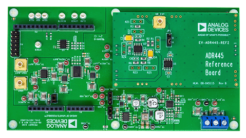
Both the EVAL-AD5781ARDZ or EVAL-AD5791ARDZ facilitate fast prototyping of the AD5781 and AD5791 circuits, thereby reducing design time. Both the EVAL-AD5781ARDZ or EVAL-AD5791ARDZ provides an on-board −14 V and +14 V dual power supply. The evaluation boards also utilizes external reference boards with an output voltage of +10 V and −10 V.
The EVAL-AD5781ARDZ or EVAL-AD5791ARDZ interface to the USB port of a PC via a system demonstration platform (SDP-K1) controller board. The Analysis | Control | Evaluation (ACE) software is available for download from both the EVAL-AD5781ARDZ or EVAL-AD5791ARDZ product pages. This software enables the user to program the AD5781 and AD5791, respectively. A peripheral module interface (PMOD) connection is also available that allows the connection of different microcontrollers to the evaluation boards without the SDP-K1 controller board. Note that when a microcontroller is used through the PMOD connection, the SDP-K1 controller board must be disconnected, and the user cannot use the ACE software.
For full details, see the AD5781 or the AD5791 data sheets, which must be used in conjunction with this user guide when using the EVAL-AD5781ARDZ or EVAL-AD5791ARDZ evaluation boards.
Applicable Parts
Documentation & Resources
-
EVAL-AD5791ARDZ Design Files6/6/2024ZIP49 M