Using the DS2786 Battery Fuel Gauge in a 2-Cell Battery Pack
Abstract
The DS2786 stand-alone, open-circuit-voltage (OCV)-based fuel gauge has an operating range designed for a single-cell lithium-ion (Li+, Li-ion) battery pack. However, the DS2786 can also be used in a 2-cell battery pack by adding a few extra components to the typical application circuit. This application note details a circuit for using the DS2786 in a 2-cell battery pack.
Overview
The DS2786 stand-alone open-circuit-voltage (OCV)-based fuel gauge estimates available capacity for lithium-ion and polymer batteries based on the cell voltage in an open-circuit state following a relaxation period. The OCV is used to determine relative cell capacity based on a lookup table stored in the IC. This capability makes accurate capacity information available immediately after a battery pack is inserted.
While the DS2786's operating range is designed for use with a single-cell Li+ battery pack, it can also be used in a 2-cell battery pack with the addition of a few components. This application note details a circuit that only requires two additional ICs to utilize the DS2786 in a 2-cell battery pack. This circuit allows the use of all the DS2786's features, including on-chip voltage, current, and temperature measurement; two auxiliary voltage inputs; and a two-wire interface.
Circuit Description
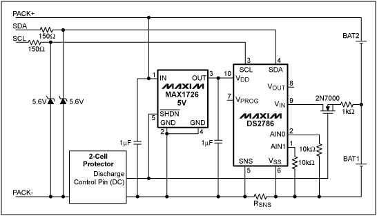
Figure 1 illustrates a circuit for using the DS2786 in a 2-cell battery pack on the cell side of the protector. The circuit shown in Figure 1 adds two additional integrated circuits to a standard DS2786 circuit: a low-dropout linear regulator (LDO) and a 2N7000 FET.

Figure 1. A circuit for using the DS2786 in a 2-cell lithium-ion/polymer pack.
Because the 2-cell battery pack's voltage exceeds the maximum operating voltage of the DS2786's VDD pin, a low-power regulator is necessary to supply VDD with an acceptable voltage. The example circuit uses a MAX1726EUK5 LDO to provide the regulated voltage. This regulator has a typical operating current of 2µA and only 0.7µA when in shutdown mode, thus making it ideal for battery-powered applications. The 5V version of the LDO is used to ensure that the voltage on the DS2786's VDD pin remains greater than the VIN pin. The capacitors on the input and output of the LDO are data-sheet recommended for stability.
The 2N7000 FET is used to switch in the BAT1 voltage level to the DS2786's VIN pin. This provides the DS2786 with a measurement of half the total pack voltage level. The 1kΩ resistor is placed in series with the FET as a precautionary measure to limit current in case of an accidental short circuit within the pack.
The example circuit is shown with VOUT floating and AIN0 and AIN1 tied low through resistors. These pins could be used as described in the DS2786 data sheet, if desired. To enhance ESD protection, we have added 150Ω resistors and 5.6V zener diodes on SCL and SDA.
Operation
When the circuit in Figure 1 is operating normally, the DC pin of the protector is high. This drives the MAX1726's active-low SHDN pin high, which enables the LDO. When the LDO is enabled, the 5V output becomes active and the DS2786 is enabled. The DC pin also drives the gate of the 2N7000 high, which turns on the 2N7000 and allows the BAT1 voltage level to pass to the VIN pin. When the DS2786 is in active mode, the VIN pin is sampled and the OCV-based fuel-gauging algorithm is executed. The user also has full access to the DS2786 through the SCL and SDA pins.
If a discharge fault condition occurs, the protector's DC pin is driven low, which disables the LDO and turns off the DS2786. The 2N7000 gate is also driven low, which stops the BAT1 voltage from passing to the VIN pin of the DS2786. Because the DS2786 is off, the only extra current drawn from the battery pack is the LDO shutdown current of 0.7µA (typ).
If an overcharge condition occurs, the protector's CC pin is driven low, which opens the charge FET. The open charge FET protects the LDO from experiencing any overvoltage conditions, and the DS2786 remains enabled.
Considerations
The DS2786 provides battery pack capacity estimates based on the open-circuit voltage presented at the VIN pin. Because the circuit in Figure 1 only measures the voltage on one cell, the voltage-based capacity lookup table stored in the DS2786's EEPROM must be modified appropriately. The voltage and capacity values obtained by characterizing the battery pack should be stored in EEPROM with the voltage level divided by 2. For example, if the battery pack has a capacity of 80% at 8V, the stored value should be 80% at 4V.
The current path feeding the BAT1 voltage to the VIN pin of the DS2786 adds an additional small load to the BAT1 cell that BAT2 does not experience. The average load current into VIN was measured in the lab to linearly increase from 5nA to 9nA when BAT1 was swept from 2.5V to 5V. The maximum 9nA results in 9nAh of capacity per hour, which is 9nAh × 24 = 216nAh per day. In a year this is 216nAh × 365 = 78.84µAh; if the user assumes a 10 year life of the pack, this is 78.84µAh × 10 = 788.4µAh. This amount of cell mismatch is negligible and should not harm the battery pack.
Summary
The DS2786 is designed for a single-cell lithium-ion battery pack but can be easily adapted to a 2-cell pack. The circuit described in this application note adds only two integrated circuits and an additional current draw of 2µA (typ). By implementing the described circuit, the 2-cell pack is able to use all of the features of the DS2786 for stand-alone OCV-based fuel gauging.