AN-1451: RS-485 Fail-Safe and Loss of Signal Detector for Energy Metering Applications
Introduction
Energy metering communication ports, which commonly use RS-485 interfaces, can be subjected to large common-mode noise, ground potential differences, and high voltage transients. In particular, over long cable runs between the master node (the central data collection point) and the energy meter slave, these hazards can either corrupt data communication or even cause permanent damage to the RS-485 interface.
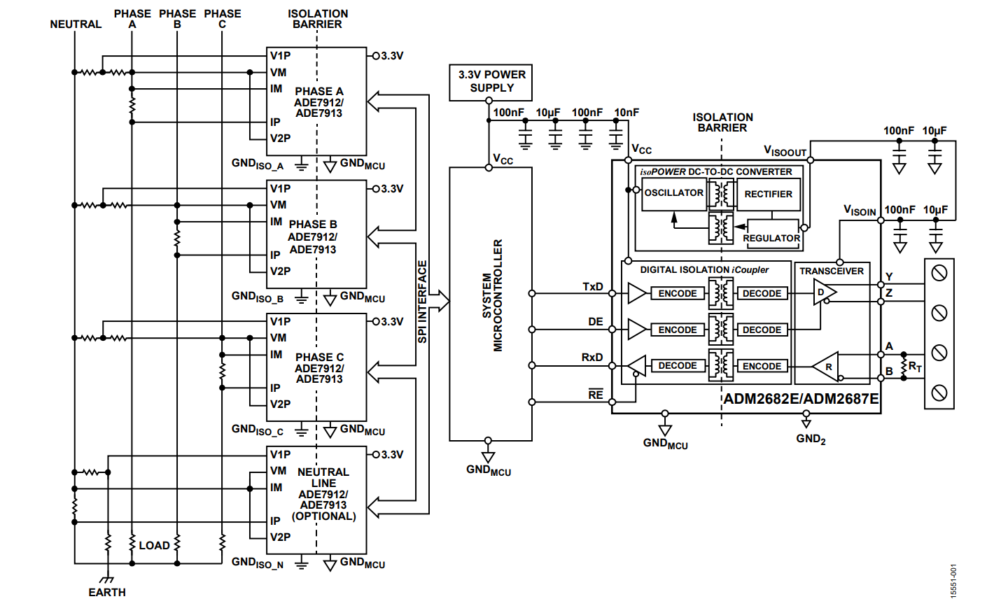
Figure 1 shows the possible isolation domains in a 3-phase energy metering slave node. The isolation barrier can either be placed at the analog front end (AFE) or at the RS-485 communications port. Use the 3-phase AFE with the ADE7912 or ADE7913 to isolate the communications interface and to measure voltage and current on Phase A, Phase B, and Phase C. The RS-485 transceiver isolates the 3-phase slave node from the master node, and allows reliable control and data transmission between the master node and the energy meter slave node. Regardless of where the isolation barrier is placed, Analog Devices, Inc., iCoupler® technology provides reliable operation in the presence of system grounding differences, common-mode noise, and voltage transients.
Higher level energy metering standards that use RS-485 as the physical layer, such as IEC 62052-11 and IEC 62053-21 (alternating current static watt-hour meters for active energy Class 1 and Class 2) specify a defined output state for when the RS-485 receiver operates on an idle bus (no active signaling). The ADM2682E iCoupler signal and isoPower® isolated RS-485 transceiver features a true fail-safe feature, offering a logic high receiver output feature for bus idle, open circuit and short-circuit conditions. Additional system diagnostics can be added to the RS-485 node if a bus loss of signal (LOS) detector circuit is used.

Fail-safe and Hystersis
Bus Idle, Open Circuit, and Short-circuit Fail-safe
The ADM2682E/ADM2687E have a true fail-safe feature, offering a logic high receiver output feature for bus idle, open circuit, and short-circuit conditions.
The open circuit fail-safe ensures that the ADM2682E or ADM2687E receiver output is high when the RS-485 A and B pins are disconnected, with no termination resistor or other nodes. This feature is present on all Analog Devices RS-485 transceivers. There is an internal pull-up resistor on the ADM2682E A pin. If the A pin is disconnected and floating, then this pull-up resistor pulls the A pin to greater than −30 mV. There is also a pull-down resistor on the ADM2682E B pin. If the B pin is disconnected and floating, this pull-down resistor pulls the B pin to less than −200 mV. In this scenario, the A pin voltage is greater than the B pin voltage, which creates a bus differential high voltage, and the receiver output is a constant logic high.
The short-circuit fail-safe ensures that the ADM2682E or ADM2687E receiver output is logic high when two nodes are driving the bus to opposite levels, or when the bus lines are shorted together.
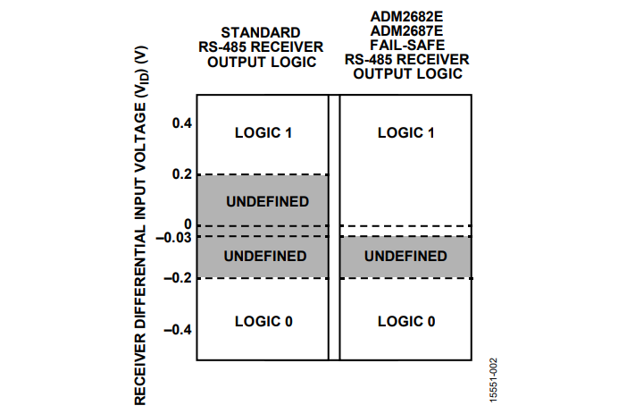
The bus idle fail-safe is more complex, and provides a logic high ADM2682E or ADM2687E receiver output when no node is driving a signal on the RS-485 bus. There are two main methods of providing this fail-safe. The first is a fail-safe RS-485 transceiver that has an offset receiver threshold, for example, of −30 mV rather than the TIA/EIA-845-A RS-485 standard 200 mV. Analog Devices RS-485 transceivers with a bus idle fail-safe also have a short-circuit fail-safe. The second method is to use pull-up and pull-down resistors on the bus to ensure a minimum differential voltage. This method is also called active or powered termination. Calculate the resistor value required based on the supply voltage and bus load, including termination resistors and receiver impedances.

Hysteresis
The TIA/EIA-845-A RS-485 standard suggests that RS-485 transceivers implement measures to prevent instability or oscillatory conditions in the receiver device. Receiver hysteresis helps improve receiver stability and provides a measure of noise immunity, which is especially important for long cable runs and harsh field bus environments.
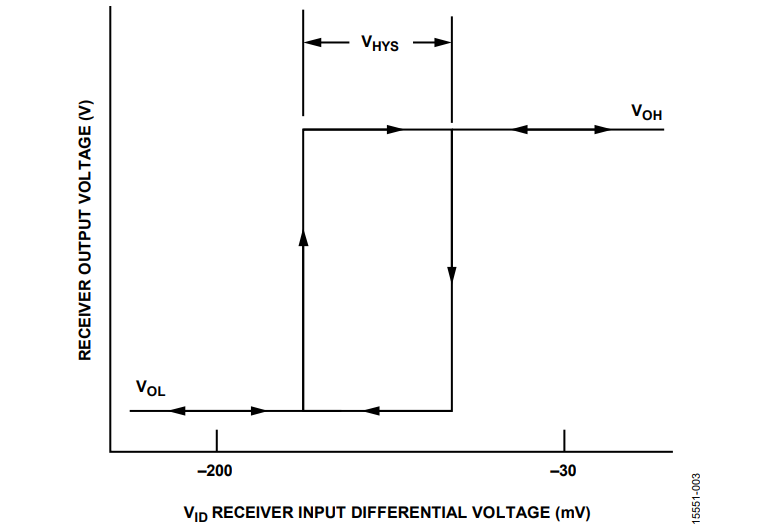
The ADM2682E/ADM2687E data sheet specifies a typical receiver hysteresis (ΔVHYS) (cap “hys” here) of 15 mV, with a receiver differential input threshold voltage range (VTH) of −200 mV to −30 mV. The VTH is the threshold for the receiver output voltage (VRO) to change from high to low, or from low to high. ΔVTH is essentially the difference between VTH for high to low (left hand side in Figure 3), and VTH for low to high (right hand side in Figure 3).
The receiver hysteresis, ΔVTH,helps ensure that noise around the receiver differential input threshold voltages (VTH) does not result in spurious logic high or logic low transitions on the receiver output.

RS-485 Loss of Signal (LOS) Detector
Nonisolated Implementation
An LOS detector alerts the system microcontroller if a connector disconnects from a slave energy meter node, or if an RS-485 cable is disconnected in error. Figure 1 shows that the system isolation barrier can either be placed at the AFE or at the RS-485 communications port. If the isolation barrier is placed at the AFE, the system designer can implement a nonisolated LOS detector circuit.
A nonisolated RS-485 LOS detector circuit isshown in Figure 4. The LOS detector circuit consists of a second ADM3078E transceiver that is used to monitor the bus state in real time. The LOS detector circuit also includes a simple NC7S08 AND gate connected to the RO pin of both ADM3078E devices. The output of the NC7S08 AND gate is then low-pass filtered with a resistor, R, and a capacitor, C. The output of the low-pass filter, which is the LOS logic signal, is wired directly to the system microcontroller.
The ADM3078E receiver can detect a valid high input from the RS-485 bus during normal operation, and output a logic high on the RO receiver output. The ADM3078E receiver fail-safe feature also outputs a logic high for bus, open circuit, shortcircuit and idle conditions. An LOS detector circuit specifically alerts the system microcontroller when there is no signal on the RS-485 bus for an extended time period.
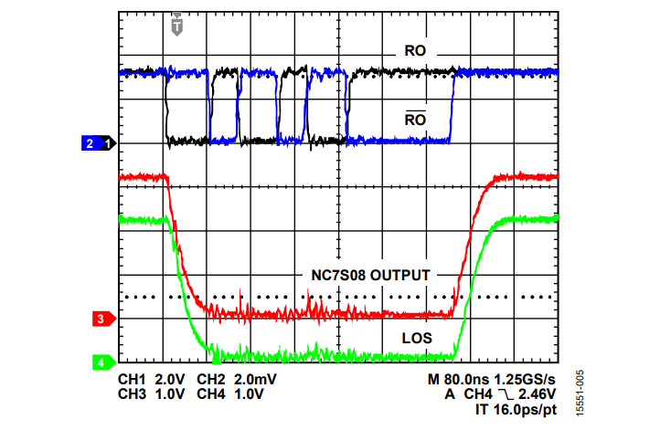
The LOS circuit shown in Figure 4 consists of two ADM3078E receiver outputs, RO and RO, which are wired to the NC7S08 AND gate. The AND gate output equals logic high when both RO and RO are in the same logic state, indicating that the bus voltage is 0 V (there is no signal on the RS-485 bus).
Differences in receiver propagation delay between the two ADM3078E receiver outputs can lead to spurious glitches on the output of the NC7S08 AND gate. The ADM3078E data sheet shows that the receiver propagation delay is a maximum of 75 ns. In typical lab measurements, the receiver propagation delay may be 40 ns. For a typical lab measurement, there may be 35 ns of propagation delay difference between the RO output and the RO output. For this measurement setup, using a lowpass filter with a 27 Ω resistor and a 220 pF capacitor compensates for this typical 35 ns difference
Adding a second ADM3078E node to monitor the bus LOS causes a reduction in the effective number of nodes that can be supported on the RS-485 network.
The system designer must consider the bus idle time period in normal bus traffic, and design a timing delay in the microcontroller LOS fault alert software to account for this. The delay prevents bus idle conditions from triggering a false LOS fault alert for the system.

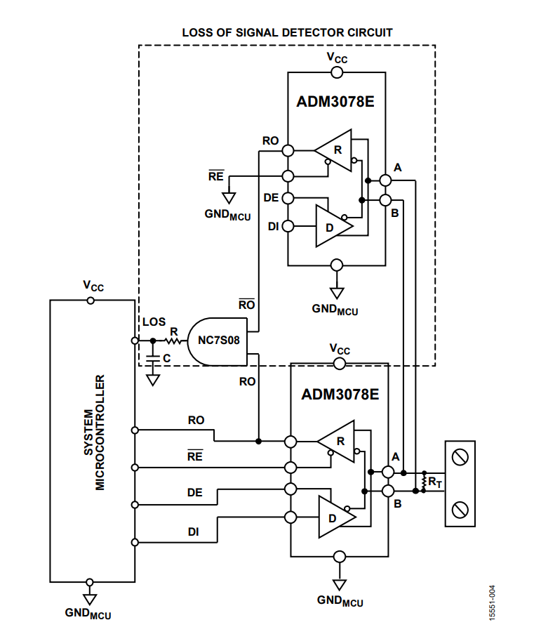
Figure 5 shows the measured signals corresponding to the circuit shown in Figure 4. The LOS logic output to the system microcontroller is logic high for the specific condition where there is no signal on the RS-485 bus.

Isolated Implementation
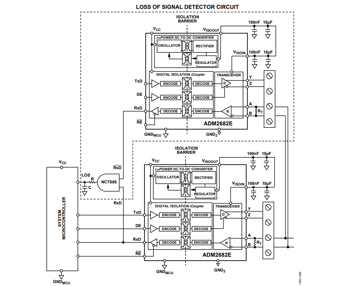
Figure 1 shows that the system isolation barrier can be placed either at the AFE, or at the RS-485 communications port. If the isolation barrier is not placed at the AFE, the system designer can implement an isolated LOS detector circuit. An isolated RS-485 LOS detector is shown in Figure 6.

Author
