

MAX20413
RECOMMENDED FOR NEW DESIGNS2.2MHz Sync Boost and Step-Down Converters with Programmable Watchdog
- Part Models
- 2
- 1ku List Price
- price unavailable
Overview
- Multiple Functions for Small Size
- Synchronous 750mA Boost Converter
- Fixed from 3.8V to 8.5V in 100mV Steps
- Synchronous Buck Converter Up to 3A
- Fixed from 0.8V to 3.8V in 25mV Steps
- External Resistor-Adjustable
- Programmable Windowed Watchdog
- 3.0V to 5.5V Operating Supply Voltage
- 2.2MHz Operation
- Individual Channel RESET_ Outputs
- High-Precision for ASIL Applications
- ±2% Output-Voltage Accuracy (OUT1) and ±1.5% Output-Voltage Accuracy (OUT2)
- ±1.5% Overvoltage/Undervoltage Monitoring Accuracy
- Excellent Load-Transient Performance
- Diagnostics and Redundant Circuits
- ASIL-C Compliant
- Redundant Reference
- Fail Safe on Open Pins
- Shorted-Pin Detection on RESET1/RESET2
- Input Overvoltage Detection
- Robust for the Automotive Environment
- Current-Mode, Forced-PWM and Skip Operation
- Overtemperature and Output Short-Circuit Protection
- 4mm x 4mm 24-Pin TQFN with Exposed Pad
- -40°C to +125°C Automotive Temperature Range
The MAX20413 is a high-efficiency, two-output, low-voltage DC-DC converter. OUT1 boosts the input supply up to 8.5V at up to 750mA, while a synchronous step-down converter operates from a 3.0V to 5.5V input voltage range and provides a 0.8V to 3.8V output voltage range at up to 3A. The boost converter achieves ±2% and the buck converter achieves ±1.5% output error over load, line, and temperature range.
The IC features a 2.2MHz fixed-frequency pulse-width modulation (PWM) mode for better noise immunity and load-transient response, and a pulse-frequency-modulation mode (skip) for increased efficiency during light-load operation. The 2.2MHz frequency operation allows for the use of all-ceramic capacitors and minimizes external components. The programmable spread-spectrum frequency modulation minimizes radiated electromagnetic emissions. Integrated low RDS(ON) switches improve efficiency at heavy loads, and make the layout a much simpler task with respect to discrete solutions.
The IC’s step-down regulator can be configured with either a factory-preset or resistor-adjustable output voltage (see the Ordering Information/Selector Guide for options). Other features include soft-start, overcurrent, and overtemperature protections.
Documentation
Data Sheet 1
Request an NDA
Complete documentation is available upon completion of a Non-Disclosure Agreement (NDA). To request an NDA, click here.
ADI has always placed the highest emphasis on delivering products that meet the maximum levels of quality and reliability. We achieve this by incorporating quality and reliability checks in every scope of product and process design, and in the manufacturing process as well. "Zero defects" for shipped products is always our goal. View our quality and reliability program and certifications for more information.
| Part Model | Pin/Package Drawing | Documentation | CAD Symbols, Footprints, and 3D Models |
|---|---|---|---|
| MAX20413ATGC/V+ | 24-TQFN-4X4X0.75 | ||
| MAX20413ATGC/V+T | 24-TQFN-4X4X0.75 |
This is the most up-to-date revision of the Data Sheet.
Software Resources
Can't find the software or driver you need?
Request a Driver/SoftwareEvaluation Kits
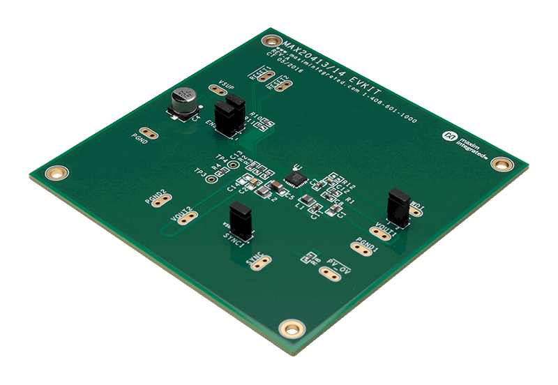
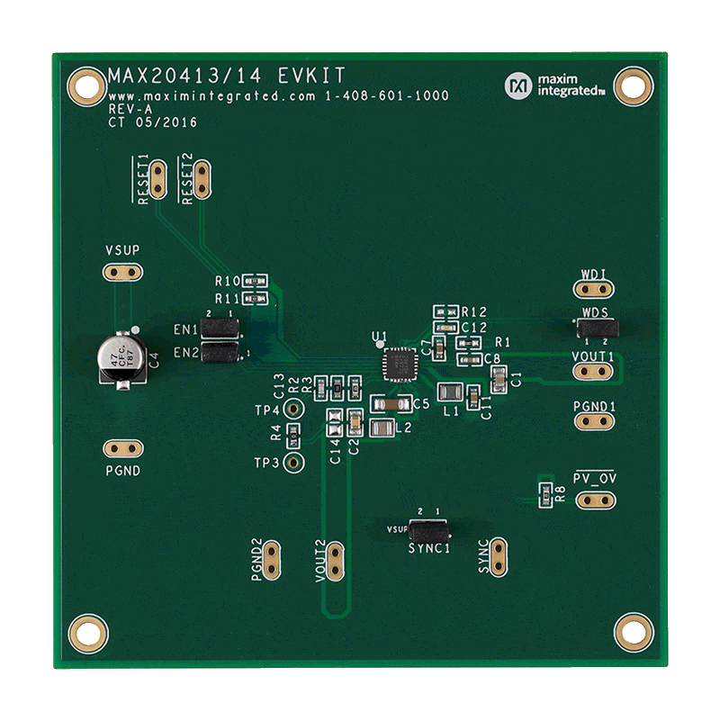
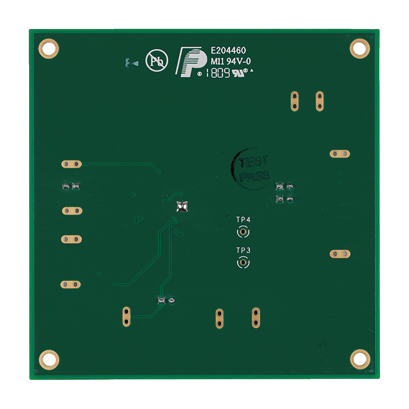
Evaluation Kit for MAX20431
Resources
Latest Discussions
No discussions on MAX20413 yet. Have something to say?
Start a Discussion on EngineerZone®