

MAX17527A
RECOMMENDED FOR NEW DESIGNS5.5V to 60V, 6A Power Limiter with OV, UV, Reverse Polarity, Loss of Ground Protection
- Part Models
- 2
- 1ku List Price
- Starting From $3.99
Overview
- Robust Protection Reduces System Downtime
- Wide Input-Supply Range: +5.5V to +60V
- ±4% Accurate Programmable Current Limit between 3A to 6A Across Full Temperature Range
- ±5% Accurate Programmable Current Limit between 0.6A to 6A Across Full Temperature Range
- ±7% Accurate Power Limit at 100W, 24V for Class 2 Applications.
- Input-Voltage Reverse-Polarity Protection (with External nFET)
- Dual-Stage Reverse-Current Protection (with External nFET) with fast 108ns response time
- Low RON Internal nFET (30mΩ)
- Output-Voltage Reverse-Polarity Tolerant
- Loss of Ground Protection
- Flexible Design to Maximize Reuse and Minimize Requalification
- Adjustable UVLO and OVLO Thresholds
- ±3% Accurate SETI Current Read-Out
- Programmable Overcurrent Response: Continuous, Autoretry, and Latch-Off Modes
- Logic Level Enable Input (EN)
- Protected External nFET Gate Drive
- Open-Drain Fault Indicator, FLAG
- Continuous Current-Limit During Startup
- Thermal Foldback Current-Limit
- Reduced Solution Footprint
- 20-Pin 5mm x 5mm TQFN-EP Package
- Integrated nFET for Common-Use Protection Requirements
The MAX17527A offers adjustable protection boundaries for systems against input voltage faults and overcurrent faults. In addition, the MAX17527A offers a programmable power limiting function. Input-voltage faults (with positive polarity) are protected up to +60V by an internal nFET featuring low ON-resistance (30mΩ typ). The device features fixed or programmable overvoltage lockout (OVLO) and undervoltage lockout (UVLO) thresholds by using internal or external voltage-dividers. Factory preset internal fixed thresholds can be invoked by connecting the OVLO and/or UVLO pin(s) to GND. Input undervoltage protection can be programmed between 5.5V and 59V, while the overvoltage protection can be independently programmed between 6V and 60V.
Input reverse-polarity protection is realized using an external nFET that is controlled by the MAX17527A. The magnitude of reverse-polarity voltage protection is dependent on the operating load-bus voltage (VOUT) and the voltage blocking capability of the external nFET. For example, for protection down to a -55V input range with VOUT = 30V, an external nFET rated at 85V is needed. The external nFET is also needed for the optional reverse-current protection. If reverse polarity protection and reverse-current protection are not needed, SN must be connected to IN and GN must be left unconnected. The MAX17527A is tolerant against accidental output reverse-polarity application due to incorrect wiring across the output terminals.
The current limit of the device is programmed by connecting a resistor from the SETI pin to GND. The current limit can be programmed from 0.6A to 6.0A. When the current through the device reaches or exceedes the set current limit, the resistance of the internal nFET is modulated to limit the current. The device offers three current limit behavioral modes: Continuous, Auto-retry, and Latch-off modes.
The SETI pin presents a current proportional to the device current under normal operation. Together with the current limit program resistor (between SETI and GND), the SETI pin presents a voltage that is proportional to the device current. This voltage can be read by a monitoring system for recording instantaneous current of the device.
The power limit function is realized either at the input supply side or output load side by sampling the input or output voltage through a potential divider connecting to the PLIM pin. The power limit feature reduces the programmed current limit when the external voltage increases above the programmed threshold. The device can be turned On or Off through enable input EN by a master supervisory system. This allows the master supervisory system to Turn On or Off the power delivery to connected loads.
The device offers loss-of-ground protection where it safely turns Off the device operation during a loss-of-ground fault event, i.e., when the safety ground fuse opens up in a redundant-safety application.
The device offers a status announcement signal FLAG) to indicate operational and fault signals. FLAG is an open drain pin, and requires an external pullup resistor to the appropriate system interface voltage. The device also offers internal thermal shutdown protection against excessive power dissipation.
APPLICATIONS
- Loss of Ground Protection
- UL1310 Class 2 Power Limiter
Documentation
Data Sheet 1
ADI has always placed the highest emphasis on delivering products that meet the maximum levels of quality and reliability. We achieve this by incorporating quality and reliability checks in every scope of product and process design, and in the manufacturing process as well. "Zero defects" for shipped products is always our goal. View our quality and reliability program and certifications for more information.
| Part Model | Pin/Package Drawing | Documentation | CAD Symbols, Footprints, and 3D Models |
|---|---|---|---|
| MAX17527AATP+ | 20-Lead TQFN (5mm x 5mm x 0.75mm) | ||
| MAX17527AATP+T | 20-Lead TQFN (5mm x 5mm x 0.75mm) |
| Part Models | Product Lifecycle | PCN |
|---|---|---|
|
Apr 20, 2026 - 2571D PIN/ERRATA |
||
| MAX17527AATP+T | PRODUCTION | |
This is the most up-to-date revision of the Data Sheet.
Software Resources
Can't find the software or driver you need?
Request a Driver/SoftwareEvaluation Kits
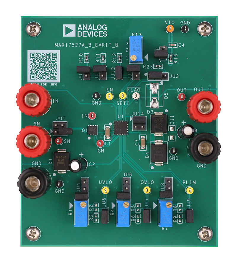
Evaluates: MAX17527A – 5.5V to 60V, 6A Power Limiter with OV, UV, Reverse Polarity Protection
Latest Discussions
No discussions on MAX17527A yet. Have something to say?
Start a Discussion on EngineerZone®